English
Views: 0 Author: Site Editor Publish Time: 2026-08-25 Origin: Site
Climate-resilient aftermarket cooling starts with a local duty profile and the conditions seen by the component—not a universal number added to ambient temperature. For distributors, fleet operators, importers and sourcing teams, that profile determines part specifications, validation, regional stock, maintenance and warranty evidence. Buyers should define heat load, low-speed and stationary operation, heat soak, condenser/radiator inlet air, dust and debris, humidity, salt, rainfall, altitude, cleaning and maintenance. Then validate the complete heat-rejection path with ageing and fouling margin.
Hot extremes are becoming more frequent and intense across most inhabited regions, but regional hazards differ. A coastal bus, desert truck, tropical excavator and high-altitude delivery van do not need the same response. The correct programme may change core protection, fin geometry, corrosion validation, fan/control capacity, packaging, inspection interval or spare stocking—while preserving exact application and vehicle requirements.
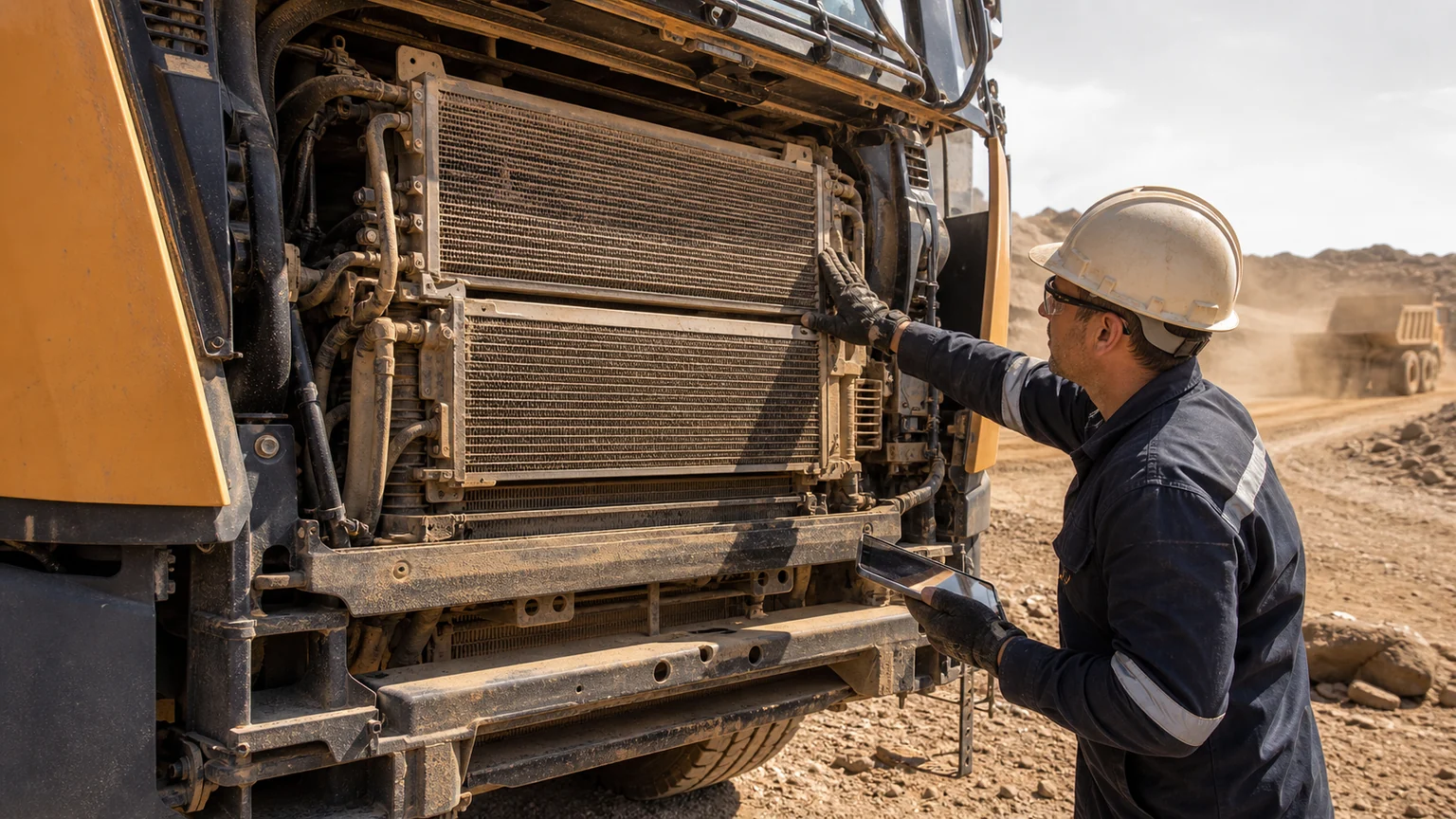
Real duty combines ambient heat, dust loading, vehicle load and maintenance access.
Collect recent and historical local temperature distributions, hot-day duration, hot nights, humidity, dust or seasonal debris, rain and flooding exposure, salt and altitude. Add operating location: urban heat islands, mines, fields, ports, tunnels, warehouses and mountain routes. Use credible regional sources and maintain a dated scenario rather than claiming one global future temperature.
Translate ambient weather to the vehicle. Solar load and heat soak raise underhood and cabin conditions. At idle, hot discharged air can recirculate to a condenser. A front stack warms air as it passes through an upstream condenser or charge-air cooler. Nearby exhaust or power electronics create local heat. Measure component inlet air where possible.
Do not design from the record maximum alone. Duration, repetition and coincidence matter: high ambient plus full A/C plus grade load plus low road speed; a hot night that prevents cooldown; or dust accumulation before the seasonal heat peak. Create operating points and time profiles.
For an engine vehicle, heat can enter coolant, charge air, oil, transmission and refrigerant circuits before being rejected by the front stack. For an EV, battery, motor/inverter, cabin, onboard charger and fast charging can share or reconfigure loops. Identify each source, allowable temperature and operating mode.
The path includes fluid flow, valves, pumps or compressor, heat exchanger, stack resistance, shroud, fan, grille and discharged-air exit. Improving a radiator cannot correct a weak pump or trapped air. A larger condenser can add air resistance that affects the downstream radiator. A fan with high free-air flow may underperform at the installed pressure.
Define heat duty, inlet/outlet temperature, flow and allowable pressure drop for each circuit and mode. For air, define inlet temperature, density/altitude, system resistance and recirculation. Unknowns should become measurement tasks, not invented specifications.
Hazard | Evidence to collect | Possible design/program response |
|---|---|---|
High ambient/heat soak | Component inlet temperatures, duration, idle/low-speed and post-soak restart | Thermal margin, fan/shroud/sealing, control calibration evidence and hot-soak validation |
Dust/debris | Particle/fibre type, loading rate, cleaning interval and observed blockage pattern | Accessible stack, screen strategy, fin choice, inspection/cleaning and fouled-state test |
Humidity/rain | Condensation, water paths, electrical ingress and storage conditions | Connector sealing, drainage, corrosion protection and package moisture control |
Salt/chemicals | Coastal/road salt, cleaning agents, fertilizer or industrial exposure | Materials/coating, galvanic control, rinse and corrosion validation |
Altitude | Route elevation, air density, grade and circuit-specific boil/cavitation margin | Fan operating-point analysis plus the pressure control, cap/degas and fill checks applicable to the actual vehicle circuit; high-altitude validation |
Flood/mud | Water depth, splash, mud packing, fan impact and contamination | Protection, drainage, service inspection and safe post-event procedure |
A “desert package” or “tropical version” should refer to this controlled envelope, not a marketing label. State which part numbers, materials, tests, maintenance and applications differ. Preserve evidence when a common design covers several regions.
One country can contain coast, desert, mountains, cities and agricultural zones. Create duty classes such as urban hot-idle, highway high-load, mining dust, agricultural chaff, coastal salt/humidity and high-altitude grade. A vehicle can belong to more than one class. Attach classes to routes, fleets and operating seasons rather than nationality alone.
For each class, list confirmed environmental ranges, heat-load modes, contamination, maintenance access and service consequence. Mark the component families most exposed. Urban hot-idle may prioritise fan, shroud and condenser airflow; mining dust may prioritise stack access, fin selection and cleaning; coastal service may prioritise corrosion and connector sealing.
Use class codes in RFQs, inventory and warranty analysis. If one severe-duty part covers several classes, retain the validation matrix. If different parts are required, prevent warehouse substitution by label and application rules. “Hot-climate version” without a defined class should not be treated as a technical specification.
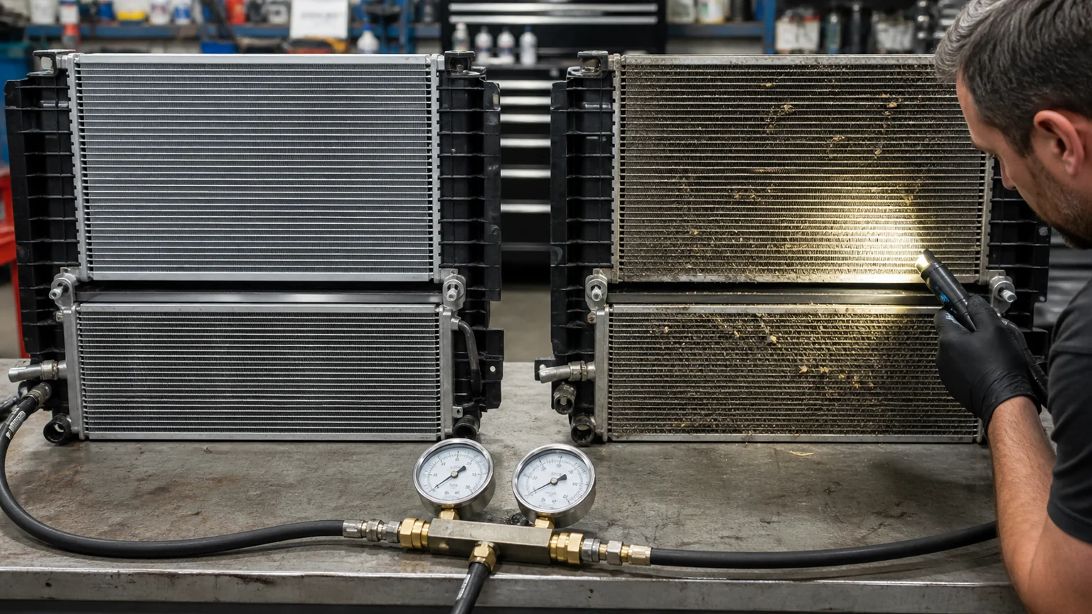
Fouling changes pressure drop and airflow even before obvious overheating occurs.
Dust, chaff, insects, fibres, oil mist and mud reduce open area and change air-side pressure drop. Stacks can trap debris between heat exchangers where external inspection misses it. Measure where blockage occurs and how quickly it develops by route and season.
Choose fin density and geometry with heat transfer, pressure drop, fouling and cleanability together. More surface area can improve clean performance but create a maintenance problem in sticky or fibrous debris. A coarse protective screen can stop large material yet add resistance or become the new blockage point. Test the installed system.
Define a fouled-state acceptance or maintenance threshold tied to airflow, pressure drop, fan current, coolant/refrigerant temperatures or visual grid. Avoid an arbitrary percentage unless it correlates with performance. A reference photograph and measured baseline can help fleets detect change consistently.
Record who cleans, where, with what water/air pressure, chemistry, direction and interval. Closely stacked cores may need access panels or separation to remove trapped debris. A workshop should not bend fins, drive contamination deeper, damage coatings, force water into controllers or release fluids into the environment.
Specify allowed methods, pressure or airflow limits, nozzles, stand-off, direction and chemical compatibility from the component and vehicle manufacturer’s applicable procedure. An acceptable method for one core or module is not a universal safe method. Excessive-pressure jets can flatten fins and breach electrical seals. Compressed air creates flying dust and may require containment and respiratory controls. Hot surfaces need cooldown before cleaning.
After cleaning, inspect fin condition, leaks, mounts, fan clearance, connectors and drainage. Compare temperature and current trends under a repeatable operating condition. If performance does not recover, investigate internal restriction, pump/fan/control or heat-source change rather than cleaning repeatedly.
Extreme events can create a sudden load outside routine maintenance. After a dust storm, inspect intake screens, grille, gaps between stack layers, fan blade/shroud and filters before demanding full load. Fine dust mixed with oil or humidity can form a mat that requires a different safe cleaning method from dry loose material.
After heavy rain or flood exposure, do not start a vehicle automatically. Follow vehicle and fleet safety procedures, especially for high-voltage systems. Inspect water and mud paths, connectors/controllers, fan movement, shroud, bearings, coolant and oil contamination indicators, and physical impact. A cooling part that is externally rinsed may still have electrical or internal damage.
Preserve event evidence for sourcing and claims: water depth and duration if known, vehicle power state, debris, attempted restart, codes, connector and fluid condition, and affected part labels. Event-related damage should not be mixed with normal product-defect statistics, but recurring vulnerability should feed design and placement improvements.
At road speed, ram air can mask a weak cooling fan or leaking shroud. Severe urban, agricultural and stationary operation needs fan-driven airflow tests. Measure inlet-air temperature at relevant core zones, fan command/speed/current, pressure or airflow, coolant and refrigerant states and vehicle load.
Discharged hot air must leave without returning to the intake. Check seals around the stack, gaps, missing underbody panels, hood/engine-bay pathways and fan rotation. A stronger fan can increase recirculation if exit resistance and sealing are poor. Smoke/tuft or pressure measurements can support diagnosis safely.
Hot restart after soak can expose vapour, electrical, sensor and control behaviour not seen in a stabilized chamber point. Define soak duration, solar or underhood condition, restart load and acceptable temperature recovery. Do not run unsafe or over-limit equipment merely to reach a data point.
High condenser inlet-air temperature raises the difficulty of rejecting cabin and compressor heat. Check condenser cleanliness, fan airflow, charge, compressor control, expansion device and evaporator/cabin airflow as a system. Static pressure or one vent-temperature reading is insufficient.
For a replacement compressor, match refrigerant, oil, architecture, ports, control, speed and operating envelope. A larger or different compressor can overload condenser capacity or vehicle power and controls. R-134a and R-1234yf service equipment and fittings must remain properly segregated.
Record high-side pressure, suction condition, vent and ambient/component inlet temperature, compressor command/current or clutch, fan status and engine/vehicle speed under defined tests. Use vehicle and component procedures for limits. A high-pressure symptom can result from airflow, overcharge, non-condensables, restriction or sensor/control issues—not automatically a defective condenser.
Heat accelerates some degradation, while humidity, salt and chemicals attack metals, joints, coatings, connectors and fasteners. Dust can retain moisture and electrolytes. Coastal salt plus industrial pollution differs from dry mineral dust. Collect deposit samples or field photographs when failures cluster.
Specify materials, brazed or welded joints, coatings and galvanic interfaces for the environment. Coating thickness alone does not prove protection; adhesion, coverage, thermal effect, damage at assembly and repair matter. Test representative complete parts with post-exposure leak, electrical and performance checks.
Packaging and storage also matter. A corrosion-resistant part can arrive wet, with damaged coating or open ports. Define barriers, caps, desiccant only where engineered, warehouse conditions and first-in/first-out or condition inspections.
Track coolant and oil temperatures, A/C pressure, component inlet air, fan command/current/speed, pump current/flow where available, vehicle speed, load and ambient. Normalise comparisons to similar operating state. A higher temperature in heavier duty may be normal; rising temperature and fan current at the same duty may indicate fouling or bearing load.
Build fleet-specific baselines from healthy vehicles. Use persistence, rate of change and multi-signal agreement. A temperature rise plus reduced airflow and increased fan current points differently from a rise plus normal airflow and lower coolant flow. Inspect before ordering parts.
Store sensor accuracy, location, units and data quality. A relocated probe or software update can create a false trend. Confirm alarms with service tools and safe physical inspection.
Engineering margin can cover variation in production, voltage, air density, coolant concentration, ageing and expected fouling. It should be allocated and verified, not expressed as an unexplained percentage. Ask what happens at the edge of the envelope: temperature stabilises at an acceptable level, fan or compressor reaches continuous limit, the controller derates vehicle load, or pressure protection intervenes.
Derating is a protective function, not automatically a defect. A fleet needs to know the trigger evidence, permitted duration, recovery condition and operational consequence. Repeated derating in normal expected duty can indicate inadequate margin, fouling, low flow, recirculation or a changed load. Do not bypass protective controls to avoid downtime.
Use availability targets with thermal targets. A design that survives the peak but requires constant maximum fan power may increase energy, noise and wear. Compare time at high command, power consumption and component temperature across clean and service-threshold conditions. This exposes a system that technically passes yet has little usable margin.
Ask suppliers which environmental and duty conditions were used in design and validation, which tests are routine, and which are type-level. Request performance curves, pressure drop, fan power, material/coating, corrosion, vibration, pressure cycle, electrical sealing and packaging evidence appropriate to the part. A certificate list without sample identity or acceptance criteria is insufficient.
Check change control. Alternate aluminium, fin geometry, coating, plastic resin, motor, controller or seal can affect heat, corrosion, fouling or cleaning. Require notice and revalidation rules. Link delivered lots to production and inspection data so a regional cluster can be contained.
Evaluate support: application data, severe-duty variants, technical response, failure analysis, spare availability and training. Regional resilience depends on diagnosing airflow, fluid, electrical and control causes, not only shipping replacement cores. A supplier should be able to state what evidence is needed before recommending a larger or different component.
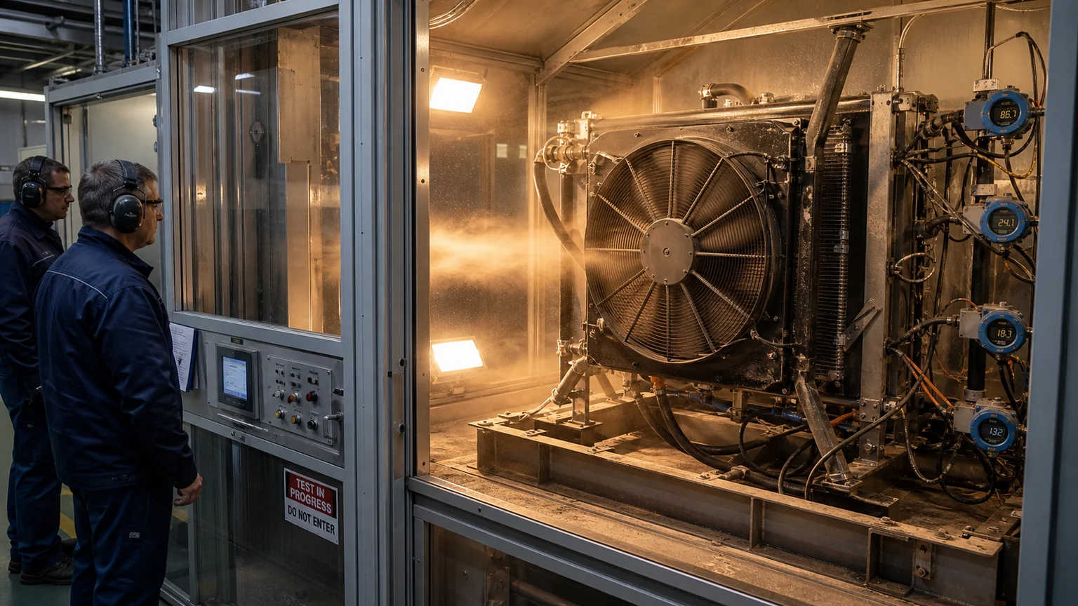
Severe-duty validation should combine heat, dust, airflow, pressure and electrical measurements.
Test block | Conditions | Outputs |
|---|---|---|
Clean thermal baseline | Defined fluid/air inlet states, flows, density and installed geometry | Heat rejection, outlet temperatures, pressure drops and power |
High ambient/idle | Hot inlet air, fan-driven flow, recirculation configuration and full loads | Temperatures, pressure, fan/compressor current and control margin |
Fouled condition | Representative safe blockage or correlated resistance | Degradation curve and maintenance threshold |
Durability | Thermal/pressure cycling, vibration, corrosion, dust/water as applicable | Leak, geometry, electrical and performance retention |
Cleaning recovery | Approved repeated cleaning process | Fin/coating condition, flow/thermal recovery and electrical integrity |
State which data are type validation, production checks or field monitoring. Test samples must represent production revision and package. Avoid combining unrelated maximum conditions into an impossible test unless the duty evidence shows they coincide.
Resilience includes availability after a heat event. Forecast regional failures using installed base, age, duty, climate season, past returns and maintenance. Pre-position critical fans, radiators, condensers, pumps, hoses, caps, sensors and compressor-related parts where lead time would extend downtime. Keep exact variants and connectors traceable.
Train distributors and workshops before peak season. Standardise evidence: application and label, ambient/inlet air, codes, fan command/current, pressure/temperature, contamination, cleaning and failure photographs. Supply fin-safe cleaning guidance, port caps, leak tools and high-voltage/refrigerant controls appropriate to the work.
Review returns after each season. Separate product defect, wrong application, debris/fouling, external control or flow cause, corrosion, transport and installation. Adjust validation, packaging, stock and training rather than assuming every hot-weather claim needs a larger part.
Before the season, clean and inspect stacks, verify fan command/current and blade clearance, check shroud and seals, confirm coolant and refrigerant service condition under approved procedures, and repair active leaks. Prioritise vehicles with previous derating, high temperature or long idle. Record healthy baselines.
During an extreme-heat period, compare operating data at known routes and loads, shorten debris inspections where evidence justifies it, and communicate safe load/idle practices. Escalate persistent over-temperature, abnormal pressure/current, reduced airflow or fluid loss. Do not recommend opening a hot pressurised system or venting refrigerant.
After the event, review which vehicles approached limits, which parts or maintenance recovered performance, and where downtime occurred. Update duty classes, stock, cleaning intervals and validation. This closed loop turns climate resilience into measurable fleet practice rather than a one-time parts upgrade.
Select representative vehicles and routes before changing the whole catalogue. Instrument healthy baselines, observe the hottest/dirtiest duty, inspect stack sealing and maintenance, then trial the proposed part or service interval. Include worst credible load and idle plus post-soak restart.
Define success as stable temperatures and pressures, acceptable fan/compressor power, controlled fouling, safe cleanability, no new leak/corrosion/vibration issue and lower downtime or claims. Record trade-offs such as added mass, resistance, noise or maintenance.
Elecdura can help structure a climate-resilient cooling-parts programme. Send route climate and altitude, vehicle/application, duty and idle, load, debris, cleaning practices, failure history, OE references, photographs and measured trends. The specification should reflect the real regional heat path and degradation—not a generic “high-temperature” label.