English
Views: 0 Author: Site Editor Publish Time: 2026-08-25 Origin: Site
A diagnostic trouble code identifies a condition detected by a controller; it does not automatically identify the failed part. A cooling-fan circuit code can be caused by the motor, control module, relay, fuse, wiring, connector, power supply, ground, command signal, mechanical obstruction, or even a mismatched replacement. A temperature or pressure code may describe an implausible signal rather than a failed radiator, condenser, compressor, thermostat, pump, or sensor.
The safest route from fault code to parts order is a structured data sheet. It preserves the code and operating snapshot before memory is cleared, records how the complaint was reproduced, captures the measurements that localize the fault, and then adds the fitment evidence needed to order the correct component. The same sheet becomes the foundation of a defensible warranty claim if the replacement later returns.
Preserve codes, freeze-frame data and the operating condition before changing the evidence.
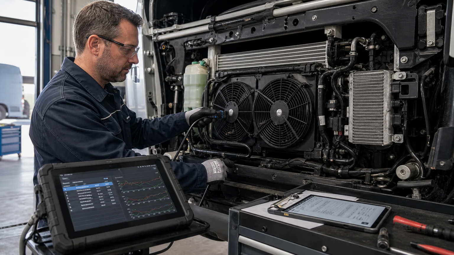
Read the complete code description, status and module. Record whether it is current, active, pending, stored, history, intermittent, or manufacturer-specific. Save freeze-frame or failure-record data when available. Then confirm the physical condition that caused the controller to set the code. Only after testing the circuit, flow path, pressure boundary, temperature response, or mechanical component should a part number enter the decision.
Do not clear codes before saving the evidence. Clearing may remove freeze-frame data, readiness information, counters, or the sequence needed to understand an intermittent fault. If a safety procedure requires power isolation or disconnection, capture the permitted scan information first. Follow the vehicle manufacturer’s service and high-voltage procedures for the specific application.
Section | Required fields | Decision value |
|---|---|---|
Asset identity | VIN/serial, model, year, engine or powertrain, market, mileage/hours, fleet ID | Separates application variants and establishes service history. |
Complaint | Customer wording, warning, operating condition, frequency, first occurrence | Defines the condition to reproduce instead of substituting a code description. |
Diagnostic record | Module, exact DTC, status, freeze frame/failure record, related codes, scan time | Preserves the controller’s detection context and code relationships. |
Reproduction | Ambient, load, speed, idle/charging state, HVAC request, warm-up state, duration | Makes before/after and warranty comparisons meaningful. |
Measurements | Voltage, current, resistance where valid, pressure, temperature, command, actual response, flow/airflow evidence | Localizes the failed circuit or heat-transfer boundary. |
Physical evidence | Leak point, fin/core condition, connector/terminal, hose/port, contamination, impact, mounting stress | Distinguishes component defect from installation, environment or adjacent-system causes. |
Part identity | OE number, supplier number, label, batch/lot, dimensions, ports, voltage, connector, control type | Supports correct matching and traceability. |
Repair scope | Failed part, required adjacent parts, flushing/cleaning, wiring repair, coolant/refrigerant service | Prevents a narrow order that leaves the cause or contamination in the system. |
Verification | Post-repair test, cleared/returning codes, measured response, leak check, road/load test | Proves whether the repair restored the intended function. |
Record the VIN or equipment serial number, model year, engine or electric powertrain, destination market, mileage or hours, and the cooling/HVAC option when known. Similar vehicle names can hide different radiators, fan controls, refrigerants, compressors, connectors, heat-pump options, or software strategies. A fleet unit number helps maintenance history, but it cannot replace the application identity used for parts matching.
Add the installed part label and OE reference before removal. If the label is damaged, photograph the installed position, ports, connectors, brackets, hose angles and dimensions. Note any previous replacement or modification. A fault that began after a recent fan, radiator, condenser, compressor, coolant, refrigerant, wiring, or software repair should be linked to that event.
Enter the exact code, not a paraphrase. Record the control module and code status. Save all related codes because a low-voltage event, communication fault or sensor reference problem can set several downstream cooling codes. Capture freeze-frame or failure-record values, including temperatures, vehicle speed, engine/motor load, voltage, fan or pump command, refrigerant or coolant pressure, and timestamps where available.
A generic code definition may be standardized, while manufacturer-specific detail, enabling criteria and test sequence remain application-specific. Use the correct service information. Do not infer that the component named in the code description is internally defective. “Fan control circuit high,” for example, describes what the controller observed at a circuit or feedback point; testing must determine whether the cause is electrical, mechanical, control-related, or a wrong part.
Write the complaint in the customer’s or driver’s words: overheats at idle with A/C on, cabin cooling weak after 20 minutes, fan runs at maximum after shutdown, charging power drops in hot weather, coolant warning appears on a hill, or compressor stops intermittently. Then define the reproduction conditions safely. Record ambient temperature, humidity if relevant, vehicle speed, load, state of charge, HVAC setting, warm-up state, idle time and route or duty.
If the condition cannot be reproduced, do not invent a failed part from the stored code. Inspect the circuit and physical system, perform approved actuator tests, review history and intermittent evidence, then decide whether further monitoring is required. An intermittent connector fault may need a voltage-drop or wiggle test under load; a thermal complaint may need a controlled hot-idle or road/load comparison. Document that the fault was not reproduced and what evidence still supports the next action.
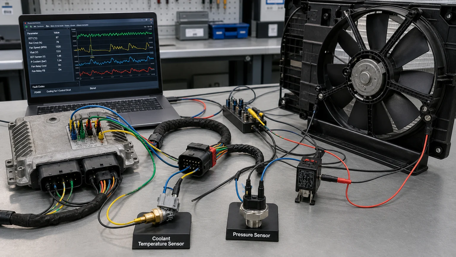
The evidence chain connects stored codes to commanded inputs, measured outputs and the actual component.
For an electric cooling fan, record supply voltage and ground voltage drop under commanded load, command/duty, actual speed when available, current, rotation direction, blade/shroud clearance and airflow condition. For a pump or control module, add connector pin condition, communication or PWM/LIN evidence, actual versus commanded response, and coolant state. Resistance checks alone may miss a high-resistance connection that fails only under load.
For a condenser or A/C compressor, record refrigerant identity, recovery/charge history, ambient condition, commanded operation, high/low pressures or approved sensor data, line temperatures, condenser airflow and verified leak location. A refrigerant-pressure-related DTC does not prove an internally restricted condenser; weak airflow, charge error, contamination, expansion control, sensor plausibility logic or another application-specific condition can create similar evidence.
For a radiator, thermostat, pump or oil cooler, separate current observations—coolant condition, level, inlet/outlet temperatures, pressure integrity, pump/engine speed, valve command and airflow—from historical records such as coolant specification, fill quantity and bleed/service procedure. High coolant temperature alone does not prove low radiator efficiency. Show whether heat entered the coolant, circulated through the component and left through airflow.
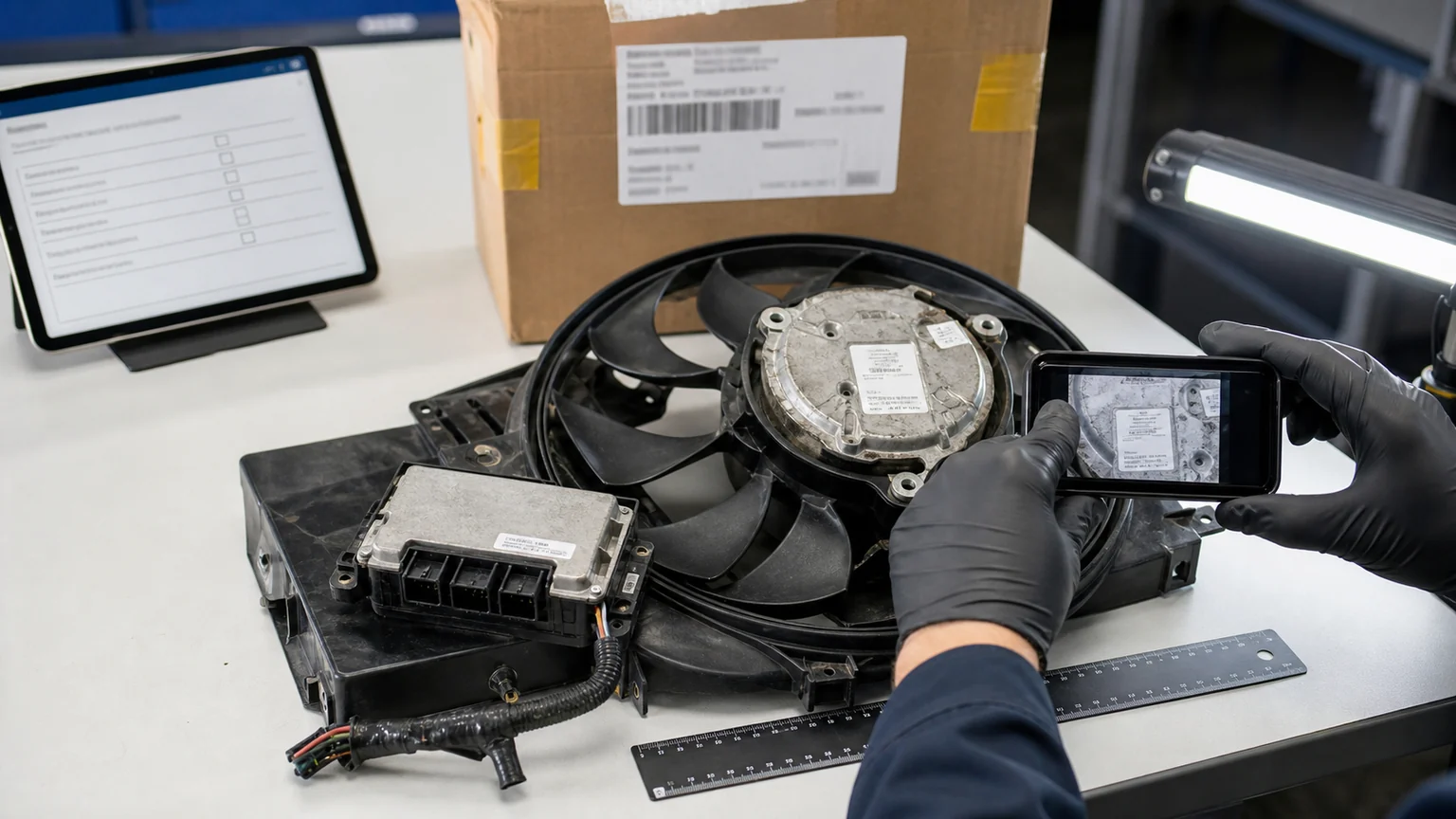
Clear photographs preserve identity, connector condition, mounting damage and handling evidence.
Use clear, original images with a scale or location reference when useful. Required views normally include the full installed component, OE/supplier label, connector face and terminals, every port or hose, mounting points, leak or damage location, surrounding components, and the removed part after safe inspection. For finned heat exchangers, photograph the front, rear, edges, manifolds/tanks and the spaces between stacked cores.
Mark a verified leak point with a removable label or annotated copy rather than damaging the part. Photograph oil, dye, coolant residue, corrosion, impact, bent fins, cracked mounts, fretting terminals, heat discoloration, debris or contamination before cleaning. Preserve the original unannotated image as well. If packaging damage is alleged, include the unopened carton, shipping label, internal protection and component position.
The order should list the confirmed failed part plus the adjacent work required to protect it. When a compressor failure releases debris or degraded oil, the repair scope may require a documented contamination assessment, an application-approved cleaning decision, replacement of non-cleanable components, receiver-drier or accumulator service, expansion-device inspection, correct oil and controlled refrigerant handling. A damaged fan connector may require a harness repair rather than only a motor. A contaminated coolant circuit may require cleaning, fluid correction and cause identification before a new radiator or pump is installed.
For each ordered item, record OE reference, aftermarket/supplier reference, application, quantity, voltage, connector, ports, dimensions, control type, included accessories and exclusions. Avoid generic descriptions such as “12 V fan” or “EV compressor.” Attach the label and interface photos to the RFQ so the supplier can challenge an incorrect match before shipment.
Record supplier, purchase order, receiving date, batch/lot/serial where available, carton condition and receiving inspection. Before installation, compare the replacement with the approved application: label, ports, connectors, brackets, dimensions, rotation/flow marks, caps, seals and included parts. Photograph the comparison without opening sealed systems unnecessarily.
During installation, record any wiring repair, flushing, coolant or refrigerant quantities, oil handling, torque or mounting sequence where relevant, bleed procedure, replaced seals and calibration/programming. If the part does not fit, stop before modifying brackets, lines or connectors. A forced installation can convert a matching error into damage that is difficult to claim.
Repeat the complaint conditions as closely and safely as possible. Confirm code status, actual component response, temperatures, pressures, current, voltage drop, airflow, leaks and customer-visible performance. A code that clears immediately is not enough; some monitors need a defined drive or operating cycle. Record pending or returning codes and do not represent a short no-fault period as a complete validation.
Keep the before-and-after measurements in the same units and locations. If the vehicle could not be tested under the original high ambient or heavy load, state the limitation and schedule follow-up. The verification field should say what passed, under which condition, and which evidence remains incomplete.
Failure | Why the claim becomes weak | Better evidence |
|---|---|---|
Code was cleared before capture | Freeze frame, status and event context may be lost. | Save complete scan and failure records before clearing or disconnecting. |
Part named in the code was replaced without circuit testing | Wiring, supply, command, sensor or mechanical causes remain untested. | Record power/ground/signal, command/actual and physical inspection. |
RFQ contains only model and symptom | Variant, interfaces and original part identity are unknown. | Add VIN/application, OE label, connectors, ports, dimensions and installed photos. |
No post-repair reproduction | There is no proof the replacement corrected the original condition. | Repeat the defined load and retain before/after data. |
A vehicle sets a fan-control code and overheats only at idle. The scan record shows high fan command. Visual inspection finds the blade free and the core moderately dirty. Under load, supply voltage is present but ground-side voltage drop is excessive; the connector shows heat discoloration. The fan motor draws normal current when powered through an approved test setup. The correct order is a connector/harness repair and core cleaning, not a fan motor. Post-repair voltage drop returns to the manufacturer-specified range or verified healthy baseline, and idle temperature remains controlled.
If the motor instead draws excessive current with rough bearings and reduced speed after the circuit is verified, the order changes to the correct fan assembly plus inspection of the module, fuse, connector and airflow restriction. The same DTC leads to different parts because measurements identify different failure boundaries.
A pressure code returns after a new compressor is installed. The data sheet shows that the original compressor failed internally, but no contamination record or flushing decision was captured. Refrigerant recovery reveals debris and the expansion device is restricted. The new compressor is not automatically the primary defect; the original repair scope was incomplete. The revised order includes the components that cannot be cleaned reliably, a controlled circuit-cleaning plan, correct drier service, oil/refrigerant specification and post-repair pressure/temperature validation.
This example shows why a warranty form must include the cause and the system preparation. A replacement part can fail or underperform because the circuit was not restored to a condition in which that part could survive.
Not every repair shop has the same tools, but every claim should meet a minimum standard. The minimum record includes asset identity, exact DTC and status, available freeze frame, complaint and reproduction condition, OE part label, connector/port photos, visible failure evidence, basic circuit or thermal measurements, repair scope, installation date and post-repair result. If a required measurement cannot be made safely or the tool is unavailable, state that limitation instead of filling the field with an estimate.
Enhanced evidence is appropriate for high-value compressors, integrated thermal modules, repeat fleet failures, bulk orders and disputed claims. It can include time-series scan logs, oscilloscope captures, commanded-versus-actual speed, current traces, pressure and temperature graphs, leak-test records, refrigerant recovery/charge printouts, coolant analysis, insulation-test results, airflow measurements, dimensional reports and retained fluid or debris samples. Enhanced does not mean collecting every possible number; it means adding the evidence that tests the suspected failure mode.
The technician should own diagnostic capture, measurements, physical findings and post-repair verification. The parts counter or purchasing team should own OE/supplier references, quantity, quoted configuration and interface confirmation. Receiving staff should own package condition, label, batch/lot and pre-installation inspection. The installer should record seals, fluids, flushing, torque, calibration and deviations. Warranty staff should confirm that the returned part matches the issued part and that evidence is attached before the claim leaves the business.
This division prevents a common failure: one person tries to reconstruct the entire story after the part has been removed, cleaned, shipped or discarded. A shared digital record can route fields to different roles while keeping one claim ID. Timestamped photographs and measurements should retain the asset and part reference so files cannot be mixed between jobs.
Use required fields only where missing data would change fitment, safety, diagnosis or warranty value. Provide drop-down choices for units and code status, but allow notes for unusual applications. Validate VIN/serial length where possible and prevent a claim from using incompatible units. Make photo prompts specific—“connector face,” “full label,” “verified leak point”—rather than requesting “more photos.”
Do not let the form substitute for technical judgment. A completed checkbox is not proof that a test was performed correctly. Supervisors should audit a sample of claims for measurement conditions, clear images, logical diagnosis and agreement between the failed boundary and ordered part. If a field is repeatedly unused or produces ambiguous data, revise the form and train the team.
The sheet may show that the fault is caused by a loose ground, contaminated connector, blocked external airflow, trapped air, incorrect refrigerant charge, wrong coolant, software/calibration issue, charger limitation or operating condition. Closing the case without a component order is a successful outcome when the evidence supports it. Record the repair or correction and verification so the next technician does not restart the same parts search.
It may also show that evidence is insufficient. In that case, specify the next test or operating condition rather than guessing. A scheduled monitoring step is preferable to fitting a high-value component that cannot be linked to the complaint. The data sheet should make uncertainty visible and actionable.
A good cooling-system data sheet preserves the controller’s evidence, adds controlled physical measurements, identifies the exact application, scopes the complete repair, and proves the result. It reduces unnecessary replacement while making genuine component claims faster to evaluate. It also gives purchasing the details needed to select the correct part the first time.
Close the record by attaching the asset, DTC, freeze-frame, measurement, photo and part-identity fields to the OE reference and required quantity. Elecdura can then assess a parts enquiry against verified interfaces and failure evidence rather than the fault-code description alone.