English
Views: 0 Author: Site Editor Publish Time: 2026-08-25 Origin: Site
A useful cooling-system RFQ tells the supplier what must be cooled, under which operating conditions, through which air and fluid paths, inside which envelope, with which ports, mounts and controls, and how compliance will be proven. Quantity and dimensions alone may support a rough conversation, but they do not define a radiator, condenser, fan, oil cooler, compressor or integrated module.
The digital form should separate known requirements, reference data, supplier proposals and unknowns. Every technical value needs units, condition, source and revision. Never fill a blank with an assumed catalogue value merely to submit the RFQ. Mark it as unknown, state who will resolve it and ask the supplier to identify the consequence or proposed test.
Distributors, importers, fleet buyers and sourcing teams can copy the rows below into a spreadsheet, sourcing portal or supplier form. Add product-specific fields from the later sections; do not delete a row merely because the answer is not yet known.
Required field | Buyer input | Supplier response | Evidence/attachment | Status |
|---|---|---|---|---|
RFQ ID, revision and date | [Enter] | Acknowledge revision | Change log | Open/accepted |
Part type and RFQ type | [Replacement match / build-to-print / development] | Confirm scope | Scope statement | Open/accepted |
Vehicle/application and OE references | [Enter exact market and variant] | Confirm or declare limits | Photos, label, official data or drawing | Blocker/open/accepted |
Media, operating states and duty | [Enter values, units and conditions] | Confirm operating envelope | Measurements, calculation or test data | Blocker/open/accepted |
Ports, mounts, envelope and interfaces | [Enter dimensions and datums] | Return controlled proposal | 2D/3D drawing and interface sheet | Blocker/open/accepted |
Airflow, electrical and control data | [Enter applicable system inputs] | Return curves and interface details | Test report, pinout or communication data | Blocker/open/accepted |
Environment, durability and validation | [Enter mission profile and acceptance] | Declare coverage and gaps | Validation plan or existing report | Open/deviation/accepted |
Quantity, schedule, destination and terms | [Enter] | Quote capacity, lead time and terms | Commercial quotation | Open/accepted |
Quality, traceability, packaging and warranty | [Enter minimum requirements] | Describe controls and exceptions | Control plan, label, pack spec and warranty | Open/deviation/accepted |
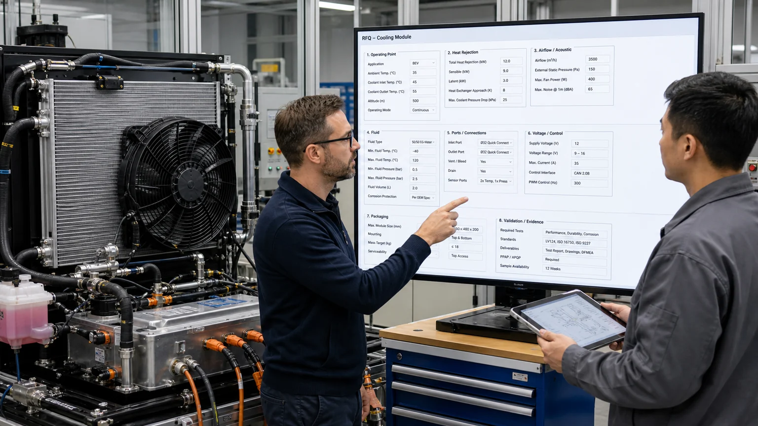
A useful RFQ connects structured commercial and engineering fields to the physical module.
A replacement-match RFQ asks for an aftermarket component equivalent to a known application or OE reference. The best evidence is the original part identity, vehicle/application, photographs, ports, connectors, dimensions, configuration and failure context. It should not quietly become a new-design project when the supplier cannot verify the cross-reference.
A build-to-print RFQ gives controlled drawings and specifications. The supplier must quote to the released revision and declare any manufacturing, material, test or tooling deviation. A performance-based development RFQ defines thermal, hydraulic, aerodynamic, mechanical, electrical, control and durability targets while allowing design proposals. It requires a clear responsibility matrix and validation plan.
A system or module RFQ covers interactions among several parts. A front-end stack may combine condenser, charge-air cooler, radiator, oil cooler, shrouds and fan. An EV loop may combine chiller, pump, valves, electric compressor and front heat exchangers. The supplier needs system resistance and control modes, not just individual nominal capacities.
Field | Why it matters | Minimum evidence |
|---|---|---|
Buyer and technical contacts | Separates commercial, engineering, quality and logistics decisions | Names, roles, email, escalation path and time zone |
RFQ/project ID and revision | Prevents quotation against an obsolete attachment | Unique ID, revision, issue date and change log |
Product/RFQ type | Defines match, build-to-print or development responsibility | Selected type and scope statement |
Quantity and schedule | Changes process, tooling, validation and capacity | Samples, pilot, annual volume, forecast horizon and required dates |
Delivery and trade terms | Affects package, freight, duties and cost comparison | Destination, Incoterm, pack quantity and delivery frequency |
Target market | Changes environment, compliance, documentation and labels | Countries, vehicle use and customer type |
Do not use a target price as a hidden technical requirement. State cost objective separately and request options with declared trade-offs. Ask for tooling, sample, test, packaging, recurring unit, core and logistics costs in separate fields. Define quotation currency, validity and what is included.
For replacement matching, collect vehicle or equipment manufacturer, model, platform, year range, market, engine or powertrain, VIN where appropriate, equipment serial, OE references and supersessions. Photographs should show the installed position, label, whole part, ports, mounts, connectors, sensors and surrounding stack. A single front photo rarely distinguishes revisions.
Name the component function and loop. Is the heat exchanger coolant-to-air, refrigerant-to-air, oil-to-air, air-to-air or refrigerant-to-coolant? Is it upstream or downstream of another heat exchanger? Does the vehicle use one coolant loop, several temperature loops, valves that reconfigure flow, or a heat-pump mode? State which architecture is confirmed and which is inferred.
List operating modes: hot idle, grade, towing, fast charging, cabin pull-down, battery conditioning, cold start, heat-pump heating, engine-off operation or emergency derate. The worst heat load may not occur at the highest vehicle speed. Low-speed or stationary airflow can be the controlling case.
Heat rejection, airflow and fluid conditions must describe one reproducible operating point.
State required heat rejection or absorption for each operating point with inlet temperatures, target outlet temperatures, mass or volumetric flow, ambient air state and permissible pressure drop. Identify whether values come from measurement, simulation, supplier estimate or energy balance. If heat duty is unknown, provide source heat, efficiency, operating power and allowable temperature limits so an engineering calculation can be reviewed.
A single “capacity” number without conditions is unusable. Heat-exchanger output changes with air and fluid temperature difference, flow, properties, fouling, installation and core construction. Specify coolant or oil concentration and properties, refrigerant, pressure states where relevant, altitude or air density and tolerance. Do not assume water test data transfer directly to glycol coolant or oil.
Define continuous, peak and transient durations. A battery chiller may face a short fast-charge peak plus a lower continuous duty. A construction radiator may face long high-load exposure with dust accumulation. State warm-up, stabilization and permissible transient temperature excursions.
For each circuit provide fluid name and specification, concentration, additives, contamination or cleanliness limits, inlet/outlet state, minimum/nominal/maximum flow, allowable component pressure drop, operating pressure, proof or burst requirement where applicable, and temperature range. Identify pulsation, reverse flow, cavitation risk, deaeration and fill/drain needs.
Ports need more than outside diameter. Record thread or quick-connect standard, sealing method, tube bead, orientation, clocking, insertion depth, mating component, allowable load and keep-out zone. Provide close photographs with scale and a drawing or scanned geometry where possible. State whether adapters are allowed and who validates them.
For refrigerant circuits, include refrigerant, oil context, high/low side, design states, compatible service fittings, cleanliness, residual moisture and leak-test requirements. A compressor or condenser RFQ must not treat R-134a and R-1234yf as interchangeable labels.
For a radiator, add tank material and features, cap or remote-degas arrangement, transmission or engine-oil cooler integration, drain, sensor/bung, bleed, core/tube/fin evidence and stack position. For a condenser, identify integrated receiver-drier, subcooling section, sensor or service features, manifold and port orientation. For a charge-air cooler, record air mass flow, inlet pressure/temperature, allowable pressure loss and cyclic pressure duty.
For an A/C compressor, add mechanical or electric drive, displacement/family, variable or fixed control, pulley/clutch geometry, rotation, speed range, refrigerant, oil, suction/discharge ports, mounting, control valve or communication, operating envelope and included accessories. Ask whether oil is supplied and how the total system amount must be determined; do not assume a pre-fill is a universal charge.
For a pump, add head-flow operating points, efficiency or power, media, cavitation margin where relevant, speed/control, dry-run limits and installation orientation. For valves, provide flow coefficient or pressure loss, leakage, port mapping, default position, actuation time, temperature/pressure, control and diagnostics. A component name without these functions leaves the supplier to guess the architecture.
A cooling fan produces an airflow-pressure relationship, not one airflow number independent of the system. The grille, guards, heat-exchanger stack, shroud, gaps, recirculation paths and underhood geometry create resistance. Provide a system resistance curve or measured pressure drop and airflow at representative conditions when available.
State fan position, push/pull arrangement, blade diameter, shroud opening, tip clearance, sealing, rotation, required operating points, vehicle ram-air contribution and noise limits. Record air density or altitude, voltage, current/power, speed and control command with each measured point. Free-air flow cannot be used as installed flow without qualification.
For a heat exchanger, include air inlet temperature/humidity if relevant, face velocity or mass flow distribution, allowable air-side pressure drop, stack order and upstream heat. A condenser can raise the radiator inlet-air temperature. A blocked or recirculating corner can create local temperature even when average flow appears adequate.
Provide maximum envelope, core dimensions, total dimensions, mass limit, centre-of-gravity concern, orientation, keep-out zones and adjacent components. Use a controlled 2D drawing or 3D file with datum and units. Photographs complement geometry but do not replace it.
For mounts, specify hole size, spacing, datum, tolerance, bushing or isolator, fastener, torque and load direction. Note whether the part carries another component. Brackets that appear cosmetic can locate a fan shroud or resist hose loads. Ask the supplier to declare welding, brazing or material changes that affect stiffness.
Include service access for caps, drain, sensors, connectors, filters, receiver-drier, hose tools and removal path. A technically fitting component can still be unusable if the connector cannot latch or a service port faces a structural member.
For motors, fans, pumps, valves and compressors, state nominal and operating voltage range, current/power limits, inrush, grounding/isolation, connector manufacturer and keying, pinout, wire size, polarity, protection, environmental sealing and electromagnetic requirements. Attach clear connector-face views and mark viewing direction.
Define control as switched, resistor, PWM, LIN, CAN, analogue, local controller or another architecture. Provide frequency, duty range, signal levels, message definitions, diagnostics, default/failsafe behaviour, wake/sleep, speed feedback and coding or calibration dependency as applicable. “Three-pin fan” is not a control specification.
High-voltage electric compressors require system voltage, connector/HVIL, insulation, grounding, communication and approved service constraints. The supplier must know whether an inverter/controller is internal, whether software is application-specific and which tests prove compatibility. Do not energise unknown equipment merely to identify it.
List ambient and fluid temperatures, thermal cycling, vibration, mechanical shock, pressure cycling, corrosion, salt, dust, mud, water, cleaning jets, chemicals, altitude, humidity and duty hours. Tie each to a test method or field profile and acceptance criterion. Avoid selecting the harshest value from unrelated standards without verifying that the combined test represents the application.
State required service life in operating hours, distance, cycles or years with duty distribution. A peak temperature and a life target need a mission profile connecting them. Define allowable degradation in leak rate, pressure drop, heat transfer, fan current, airflow, noise or appearance after durability.
Destination changes validation. Coastal salt, mining dust, tropical humidity and extreme cold create different risks. Identify severe-duty variants or shared designs and ask the supplier what design margin supports the common programme.
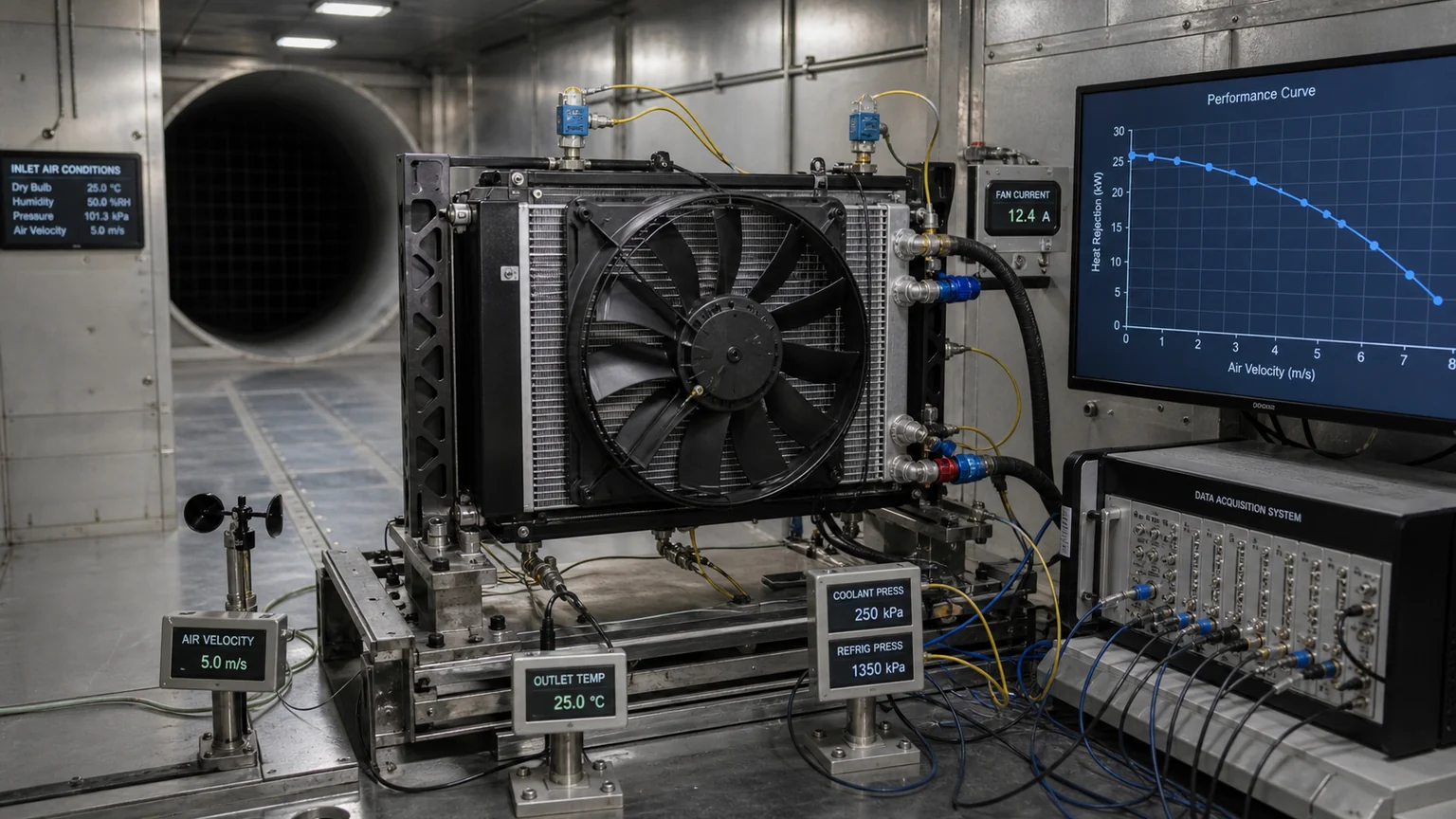
Evidence-backed approval links the RFQ to interface drawings, samples and test results.
The following levels are a practical internal sourcing framework for this template, not a universal industry-standard hierarchy. Define the terms in the RFQ so every bidder uses them consistently.
Evidence level | Meaning | Example |
|---|---|---|
Reference only | Information that guides identification but is not accepted proof | Unverified cross-reference or field photo |
Supplier declaration | Supplier confirms a defined property | Material, process or included oil statement |
Type validation | Design tested on representative samples | Thermal, vibration, corrosion or pressure report |
Production control | Routine lot or unit release check | Leak test, dimensional gauge or electrical function |
Customer approval | Buyer accepts sample and evidence for a revision | Fit, vehicle, bench or pilot approval |
Create a validation responsibility matrix: requirement, method, sample quantity, condition, acceptance, laboratory, payer, witness, report owner and due date. Mark whether evidence is existing, planned or unavailable. Type-test success does not replace stable production controls, and a routine leak test does not replace thermal validation.
Define sample identity and change control. Reports should name part and drawing revision, lot/serial, test equipment, calibration, setup, raw or summarized results, deviations, photographs and conclusion. Ask suppliers to declare differences between tested sample and quoted production.
Request manufacturing site, critical processes, quality certifications relevant to the programme, control plan, inspection, lot/serial scheme, change notification, nonconformance handling and record retention. Certifications do not replace component evidence, but they help define the system around it.
Specify cleanliness and port protection, fin/no-contact zones, individual pack, master carton, pallet pattern, labels, quantity, transport route and package-test requirement. A technically correct condenser can still arrive unusable if fins or ports carry stacking load.
Define warranty period and start, coverage, required claim evidence, response time, returned-part ownership and corrective-action expectation. The evidence schedule should be available before purchase. Request cause-coded return reporting so wrong application, transit, installation and product defects are not merged.
For every requirement, record source and confidence: measured and repeatable; controlled drawing; official service data; supplier record; field observation; or assumption. Add a status of mandatory, target, reference or open. This lets suppliers quote with visible risk instead of hiding assumptions in email.
A completeness score should weight critical fields. Missing connector pinout or refrigerant is more serious than a missing colour preference. Create red blockers for application identity, media, pressure/safety, voltage/control and interfaces; amber items for unresolved targets; green for controlled evidence. A high completeness score means the requested information is present; it does not mean the design is technically validated. The score is a triage tool, not proof of technical adequacy.
When suppliers make assumptions, require them in a dedicated deviation and assumptions table. Silence is not acceptance. Each item should state requirement, proposed value, technical/commercial effect, evidence and approval status.
A single pass point hides margin and operating interaction. Request heat rejection versus fluid and air conditions, pressure drop versus flow, fan airflow versus pressure and power, pump head versus flow, or compressor performance across the agreed envelope as appropriate. Curves should name test media, temperatures, density, speed/command and setup. They help the buyer find the actual system intersection and sensitivity.
Request tolerances or variation, not just a nominal line. Manufacturing spread, voltage, ambient density, fouling and installation leakage can move performance. Ask which variation is covered by design validation and which is controlled in production. Do not extrapolate beyond tested ranges without an agreed model and validation.
For integrated modules, require an energy and control view. A larger fan may meet airflow but consume more power or noise; a lower-resistance core may alter size or cost; a different pump point may move valve balance. Ask the supplier to show trade-offs against the system priorities defined in the RFQ.
Sample approval should define what was checked: identity, packaging, dimensions, installation, ports, electrical/control, bench performance, vehicle performance and durability. Record open items and restrictions. A sample that physically fits should not be labelled “fully approved” while thermal or software validation remains pending.
Before production release, reconcile the final drawing, bill of materials or critical characteristics, test plan, control plan, label, package and supplier quotation. Freeze the agreed revision and list permitted process/material sources where necessary. First-production verification should confirm that the delivered unit matches the approved evidence.
After launch, connect warranty and field data back to the RFQ. If actual ambient, dust, duty or system resistance differs from the original assumptions, update the application record. A strong RFQ becomes a living technical baseline for corrective action and future sourcing, not a file that disappears after purchase order.
Use structured fields for searchable facts and attachments for drawings, curves, reports and photos. Apply units and allowed formats. Keep an audit trail of who changed a requirement and why. Lock quoted revisions and issue a new revision when technical scope changes.
Do not overwrite the buyer requirement with the supplier answer. Store requested, proposed, agreed and verified values separately. A proposed lower airflow becomes agreed only after approval; it becomes verified only after the defined evidence passes. Link decisions to samples and production revision.
Protect confidential data with role-based access, controlled download and retention. Avoid placing unnecessary personal or vehicle-owner data in supplier packages. Provide the minimum VIN/application evidence required for matching and remove unrelated information.
For an urgent aftermarket match, begin with application, OE reference, full-part photos, label, ports, connectors, mounts, dimensions, refrigerant/coolant/oil, voltage/control and destination. Add the reason for replacement and photographs of the installed environment. Ask the supplier to state match confidence and open checks.
Do not let urgency erase blockers. If two variants share an OE family but use different connectors or controls, hold the order until resolved. A sample comparison can close geometry, but it does not prove thermal capacity or durability unless the programme defines that evidence.
Elecdura can help distributors, importers, fleet buyers and sourcing teams convert a cooling-parts request into this structured evidence set. Send what is known with units, conditions, sources and photographs; mark unknowns openly. A complete digital RFQ shortens clarification, exposes deviations, improves quotations and creates the baseline for sample approval, production and warranty.