You are here:Home » Blog » Technical Guides » 800V High-Voltage eFans for Electric Trucks: Motor, Inverter, PWM/CAN Control, and Cooling-Module Matching
800V High-Voltage eFans for Electric Trucks: Motor, Inverter, PWM/CAN Control, and Cooling-Module Matching
Views: 0 Author: Site Editor Publish Time: 2026-09-14 Origin: Site
An 800V eFan is a high-voltage cooling actuator, not a larger version of a 24V fan. Matching requires the continuous and transient DC voltage window, isolation strategy, motor and inverter ratings, fan performance against the installed cooling-pack resistance, direction, shroud and mount geometry, PWM or CAN command and feedback behavior, diagnostics, electromagnetic compatibility, environmental sealing, safety architecture, and thermal validation.
This guide is written for engineering teams, fleet operators, distributors, and aftermarket buyers evaluating emerging thermal products. It connects the new architecture to familiar sourcing controls used for a radiator cooling fan, off-highway thermal system, and electric A/C compressor, while keeping high-voltage, software, and battery or fuel-cell boundaries explicit.
New thermal components should be identified as complete mechanical, fluid, electrical, and control systems.
1. Why truck platforms move the fan to high voltage
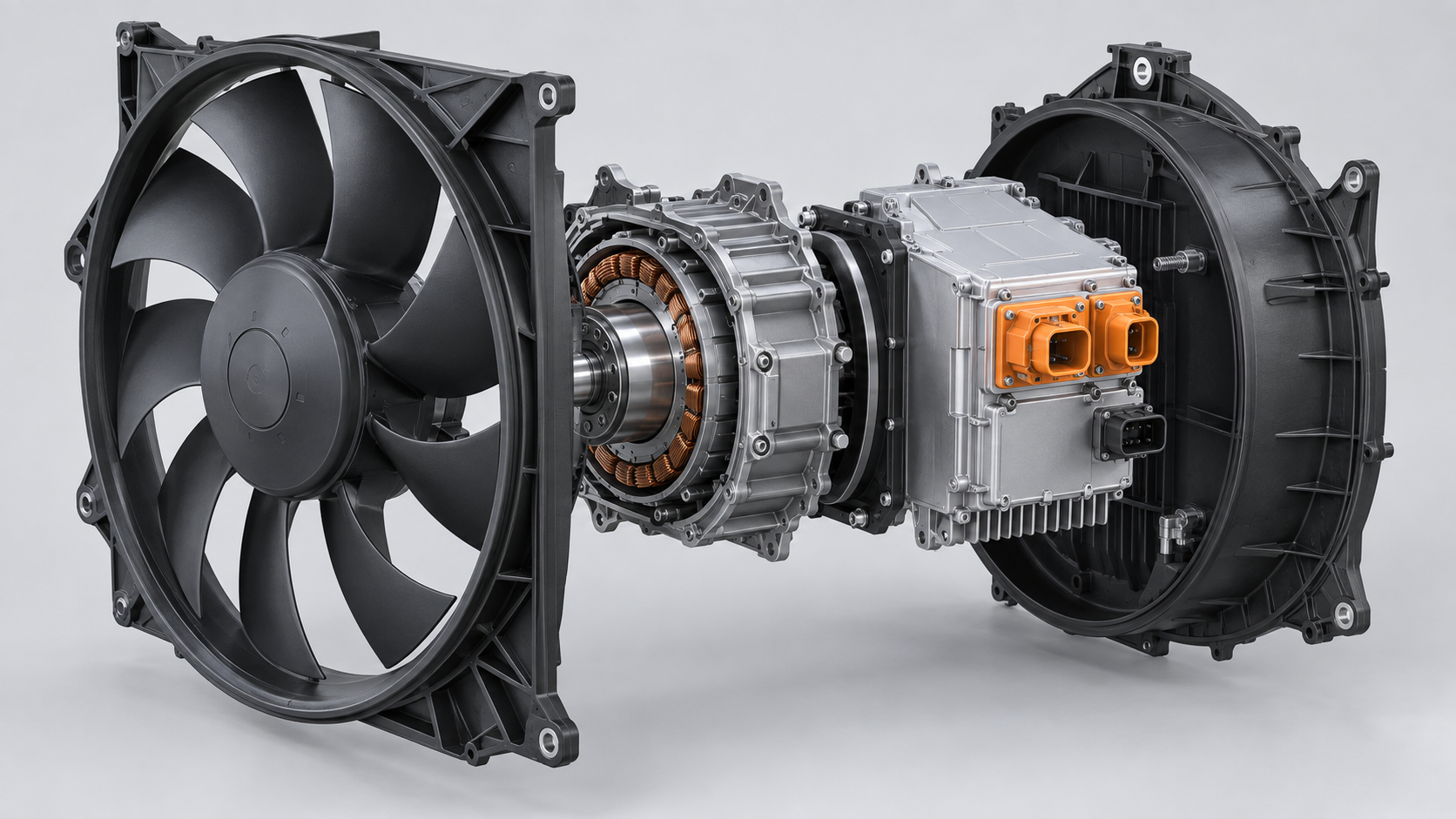
Electric trucks must reject heat from the battery, motors, inverters, e-axles, charging system, cabin loop, and sometimes a fuel-cell or range-extender system. A high-voltage fan can deliver substantial power without the very high current that an equivalent low-voltage actuator would require. Integration can combine fan, motor, and inverter into one controlled module.
This does not make every platform 800V or every eFan interchangeable. BorgWarner publicly describes a high-voltage eFan family spanning a broad 430–970 V DC range and 3–40 kW; those figures describe that supplier's family, not a universal specification. The vehicle's actual voltage and power window governs.
2. Voltage class is not the voltage window
A system marketed as 800V changes voltage with state of charge, temperature, charging, regenerative events, faults, and component operation. Record nominal, minimum operating, maximum continuous, and transient conditions, plus pre-charge and discharge behavior. Do not approve a fan from a single nameplate number.
Connectors, capacitors, semiconductors, insulation distances, sensing, and protection must suit the complete window. Ask how the inverter responds to under-voltage, over-voltage, reverse polarity on low-voltage circuits, loss of isolation, and interrupted communication.
3. Integrated motor and inverter change service boundaries
A high-voltage eFan commonly includes an electric motor, power electronics, control logic, sensing, and cooling provisions. A mechanical blade or bearing failure may be physically visible, while an inverter or software mismatch can look like a dead motor. Service documentation must define whether the module is repaired, replaced, or reprogrammed.
Record hardware and software numbers. An identical housing can contain different firmware, communication matrices, rotation limits, or diagnostic behavior. A used module from another vehicle is not proven compatible by connector fit.
4. Fan curve and system curve must meet
Free-air airflow is measured with little resistance. A truck fan works against grille, shutters, condenser, radiators, charge-air or coolant cores, guards, filters, and recirculation paths. The operating point occurs where the fan curve intersects the cooling-module system curve.
Compare airflow and power at stated static pressure, air density, speed, and voltage. Include reverse flow or ram-air conditions where relevant. Test the complete module with production seals and shroud because small bypass gaps can waste capacity.
5. PWM, CAN, and other controls are not interchangeable
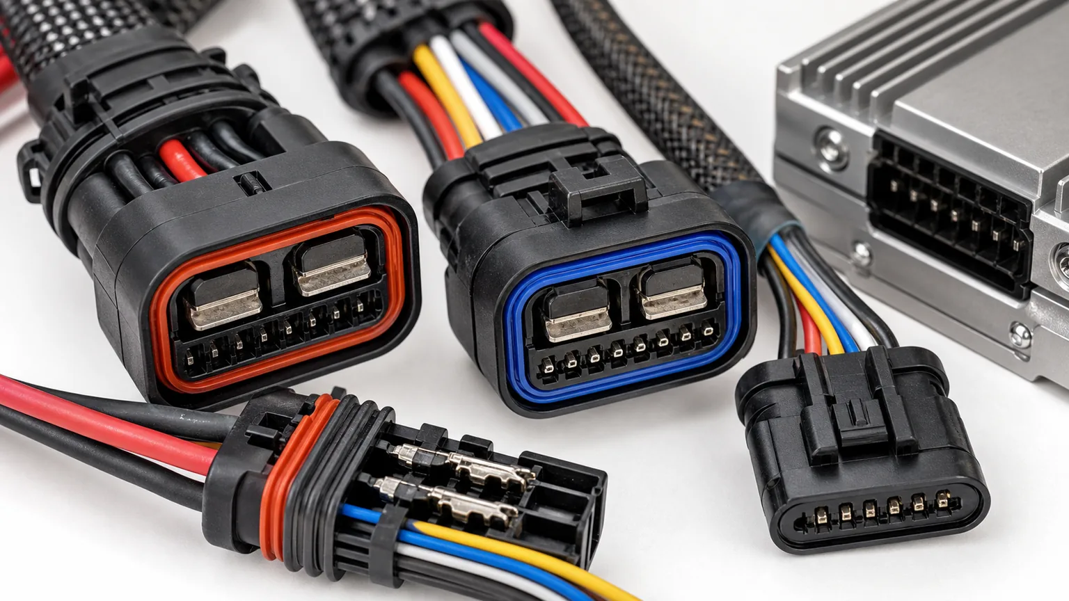
A high-voltage power connector does not tell the fan how fast to run. The low-voltage interface may use PWM, CAN, LIN, discrete enable, wake, or a proprietary protocol. Specify pinout, voltage levels, termination, frequency or message set, scaling, timeout, authentication or counter behavior, and feedback.
A fan may enter fail-safe speed when messages disappear, remain off until a valid rolling counter arrives, or limit power under internal temperature. Bench testing must reproduce the intended network and capture command, actual speed, current, status, and faults.
6. Direction, blade, and shroud remain mechanical fundamentals
Rotation should be defined from a stated viewing side. Confirm pusher or puller duty, blade sweep, hub offset, tip clearance, shroud depth, mounts, isolators, and service access. Reversing polarity is not a valid way to reverse an electronically controlled high-voltage fan.
A mechanically correct fit must not preload the shroud or place the blade close to a heat exchanger under frame twist. Electric trucks can be quiet, making fan tonal noise and structural vibration more noticeable.
Bench validation must reproduce the relevant boundary conditions and record all interacting variables.
7. High-voltage safety starts before energizing
Only trained personnel using the vehicle maker's procedure should work on high-voltage components. Isolation, lockout, discharge verification, personal protective equipment, tools, barriers, and connector interlocks belong to the plan. Never probe orange cables with ordinary workshop habits.
The fan specification should cover insulation monitoring, high-voltage interlock loop if used, creepage and clearance, connector touch protection, grounding or shielding, and safe response to faults. A product image cannot establish those controls.
8. Thermal management of the inverter matters
The inverter dissipates heat while the fan is working hardest. Its cooling may depend on airflow, housing conduction, coolant, or placement. Hot air recirculation and under-hood soak can reduce available power. Ask for derating curves and internal-temperature behavior.
Test high ambient, blocked or degraded airflow, repeated start, low vehicle speed, and charging conditions. Monitor semiconductor or controller status where available rather than judging only blade speed.
9. EMC and electrical integration affect the whole truck
Fast switching and high power can create conducted and radiated noise, while the fan must tolerate disturbances from chargers, traction inverters, contactors, and DC/DC converters. Shielding, grounding, cable routing, filtering, and software strategy are system decisions.
Require the applicable OEM and regulatory electromagnetic-compatibility plan. A module that runs on a bench may still disturb sensors or communication in the vehicle, or reset when another high-power device switches.
10. Dust, water, salt, vibration, and stone impact are application inputs
Off-highway or mining variants may require different guards and cleanability. Do not assume a road-truck rating transfers to another duty because nominal voltage is the same.
11. Diagnostics and limp-home behavior need agreement
Specify commanded speed, actual speed feedback, current or power reporting, internal temperature, fault codes, counters, and reset conditions. Decide what the vehicle should do if the fan cannot communicate or reach target speed.
A fleet needs diagnostic documentation that separates fan, network, high-voltage supply, low-voltage supply, sensor, cooling-pack blockage, and controller-command faults. Replacing the fan repeatedly does not fix a missing enable message.
12. Production approval includes software and cybersecurity change
The golden sample record should include mechanics, electronics, firmware, calibration, boot behavior, communication database, and labels. Require notification before semiconductor, motor winding, magnet, bearing, blade, connector, inverter, or software change.
End-of-line testing should verify identity, isolation, communication, direction, speed, current, vibration, and diagnostic reporting. Periodic fan-curve and environmental validation protects long-term consistency.
Evidence matrix for a sourcing decision
Layer
Evidence to retain
Approval question
Application
Vehicle or machine, architecture, duty, environment, revision
Worked example: an eFan that spins but overheats the truck
A replacement module powers up and reaches high free-air speed on a supplier bench. On the truck, coolant temperature rises during a hot uphill pull and the fan repeatedly derates. Data shows the vehicle commands maximum speed, but actual speed and power fall as the inverter temperature increases.
Inspection finds the replacement has a similar diameter and connector but a higher-resistance shroud geometry, different airflow direction definition, and firmware intended for another cooling pack. Its inverter receives recirculated hot air because a production seal does not match. The failure is not one simple motor defect; mechanical, aerodynamic, thermal, and software mismatches combine.
The corrective path restores the controlled shroud and seals, validates the CAN interface, tests the fan curve against the complete stack, and repeats high-ambient duty while logging voltage, power, speed, static pressure, temperatures, and faults. The example shows why a free-spin video cannot approve a high-voltage fan.
Recommended validation workflow
Freeze vehicle voltage window, network, cooling loads, environment, and safety requirements.
Map the cooling-module system curve and required operating points.
Confirm fan direction, shroud, mounts, clearances, connectors, interlocks, and cable routing.
Review motor, inverter, protection, derating, diagnostic, and firmware data.
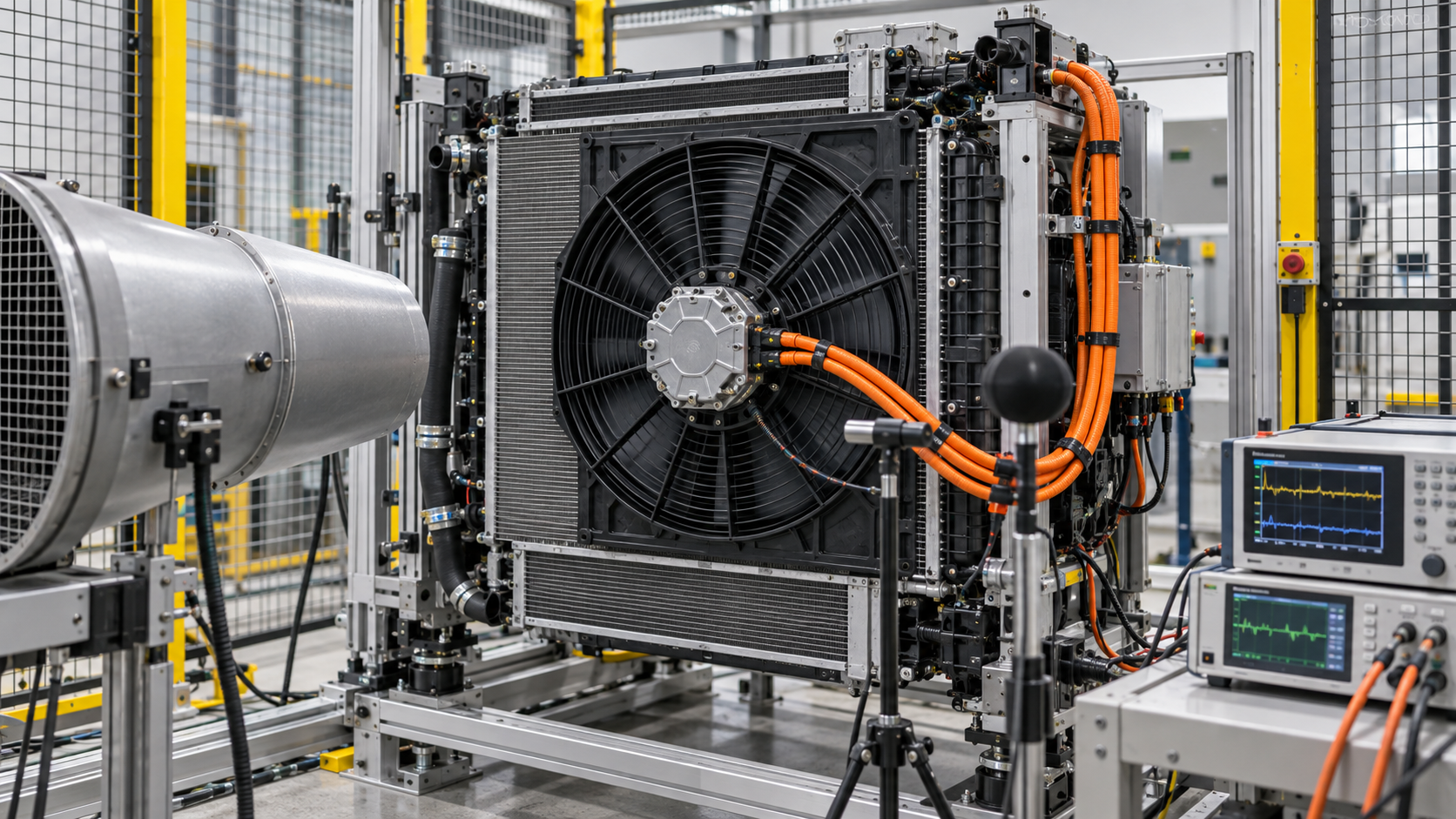
Bench the module with isolated high-voltage equipment and the intended low-voltage control network.
Measure fan curve, power, speed, vibration, acoustic behavior, and thermal limits.
Run EMC, environmental, vibration, corrosion, and durability validation to the agreed plan.
Install production seals and validate the complete truck across drive, idle, charging, and heat-soak conditions.
Approve hardware, software, end-of-line tests, traceability, packaging, and change control.
Run a formal review after each layer. A visually correct sample should not advance if its software, fluid, safety, or duty evidence is unresolved. Deviations need named owners and closure criteria rather than informal promises.
Interfaces, software, ports, and traceability belong in the approval record.
What an RFQ should include
Send the platform, annual volume, development phase, target market, duty cycle, ambient and altitude range, heat loads, electrical architecture, networks, fluids, packaging envelope, mounts, ports, sensors, safety requirements, standards, validation responsibility, sample stages, production timing, service concept, and change-control expectations. Mark confidential data and use controlled revisions.
Ask the supplier to distinguish available product, configurable family, and new engineering. Request the exact tested configuration and conditions. Do not treat a promotional product-family range as a commitment that one SKU covers the full range. For early concepts, agree which values are targets and which are demonstrated results.
Commercial comparison should include engineering, tooling, samples, validation, software support, warranty evidence, service parts, lead time, quality response, and lifecycle changes. Unit price alone cannot represent the risk of a safety-related integrated thermal component.
Receiving and change-control plan
Verify labels, hardware and software revision, connectors, ports, caps, seals, mounts, visible damage, moisture protection, and traceability at receiving. Use risk-based sampling for dimensions, leak, insulation, communication, or functional tests. Keep new or revised lots quarantined until required evidence passes.
Require written notice before changes to materials, wetted components, geometry, tooling, joining, electronics, semiconductors, motor, sensors, firmware, communication, manufacturing plant, end-of-line testing, or packaging. Decide which analysis, bench tests, and vehicle tests must be repeated. Retain representative samples and data for each approved revision.
Common approval mistakes
Selecting by nominal voltage or headline capacity alone
Assuming physical connectors guarantee electrical or digital compatibility
Comparing thermal figures at different boundary conditions
Ignoring pressure drop, pump or fan power, and control derating
Testing one operating mode while the product serves several modes
Using passenger-car evidence for heavy-duty or off-highway duty without validation
Dropping software and diagnostic revisions from the parts record
Approving a prototype without production end-of-line and change controls
Each shortcut substitutes a visible attribute for a system requirement. When information is missing, document the uncertainty and stop before energizing, charging, filling, or ordering production quantities.
Frequently asked questions
Can a similar-looking component be cross-referenced?
Only after architecture, ports, internal function, fluids, pressure class, voltage, control, software, safety, mounts, and performance are confirmed. Appearance can start identification but cannot finish it.
Are supplier product-family ratings enough for approval?
No. They show capability boundaries. Approval requires the exact SKU or configuration, test conditions, application, interfaces, and documented limitations.
Should aftermarket buyers bench-test high-voltage parts?
Only qualified teams with appropriate isolated equipment, procedures, safety controls, and technical data should do so. Otherwise use authorized test and service channels.
What data is most valuable after a field problem?
Preserve identity and software, operating mode, commands and feedback, voltages, currents, flows, pressures, temperatures, faults, fluids, installation images, and the timeline leading to the event.
When should the complete module be replaced?
Follow the vehicle or system maker's service boundary. Integrated products may contain non-serviceable or calibrated assemblies; unauthorized disassembly can create safety, contamination, and warranty risk.
Build a high-voltage eFan bench safely
A qualified bench needs an isolated and current-limited high-voltage source suitable for the module's full operating window, pre-charge where required, discharge verification, contactors, fusing, interlock monitoring, guarded rotating hardware, emergency stop, insulated measurement, and a controller that reproduces the intended low-voltage network. Keep people outside the blade and arc-flash hazard boundaries defined by the organization. A temporary battery pack, loose orange cables, and a handheld signal generator do not constitute a safe development bench.
Measure DC voltage and current at the module, low-voltage supply, commanded and actual speed, static pressure, airflow, inverter and motor temperatures, vibration, acoustic data, and diagnostic messages. Verify startup, ramp, steady operation, command loss, supply transients, blocked airflow, stall protection, overtemperature, and safe shutdown. Discharge time and residual voltage must be confirmed before touching or disconnecting the product.
How fleets should diagnose a no-cooling complaint
Begin with vehicle faults, requested speed, reported speed, high-voltage bus state, low-voltage wake supply, interlock, network status, fan power, coolant temperatures, and pressure difference across the cooling pack. Inspect grille, shutters, seals, stacked cores, shroud, blade, connectors, mounts, and cable routing. A zero-speed result can be a network or enable problem, while full speed with poor cooling can be an airflow-path or heat-exchanger problem.
Do not repeatedly command maximum speed when the blade is obstructed, bearings are damaged, insulation is suspect, or the controller reports a protective shutdown. Preserve software and hardware identity before replacement. A recovered module should be returned with the operating log, not only the description “fan not working.”
Packaging and service are part of electrical safety
Transport caps and connector protection must prevent bent interlock pins, moisture, contamination, and electrostatic or mechanical damage. The carton must support the shroud without loading blades or inverter cooling surfaces. Receiving teams should quarantine impact-damaged high-voltage modules even if the fan turns by hand. Service parts need clear revision control, safe storage, authorized installation, commissioning, and end-of-life handling.
Key conclusion
An 800V eFan is a high-voltage cooling actuator, not a larger version of a 24V fan. Matching requires the continuous and transient DC voltage window, isolation strategy, motor and inverter ratings, fan performance against the installed cooling-pack resistance, direction, shroud and mount geometry, PWM or CAN command and feedback behavior, diagnostics, electromagnetic compatibility, environmental sealing, safety architecture, and thermal validation. The right buying decision connects component evidence to the complete vehicle or machine duty and retains enough traceability to manage later changes.
For an Elecdura sourcing review, send the platform, part and software numbers, diagrams, labels, interfaces, quantities, destination, and required validation. Early clarity helps determine whether the request is a catalog match, a controlled equivalent, or a new engineering program.
Approval records should also state the complete cooling-pack part numbers and seal revision. The same eFan can operate at a different aerodynamic point when a condenser, radiator, shutter, grille, or guard changes. Treat those vehicle changes as thermal-interface changes and review whether fan-curve or high-ambient tests must be repeated.