You are here:Home » Resources » Blog » Industry Insights » Generator Oil Cooler Selection in the U.S.: Heat Load, Flow, and Fitment Checks
Generator Oil Cooler Selection in the U.S.: Heat Load, Flow, and Fitment Checks
Views: 0 Author: Site Editor Publish Time: 2026-09-23 Origin: Site
A generator oil cooler cannot be selected reliably from engine power, core dimensions, or port size alone. The correct cooler must satisfy the diesel engine's lubrication circuit, heat rejection, oil flow, allowable pressure drop, cold-start behavior, cooling-air or coolant conditions, mounting envelope, vibration duty, and service environment.
This guide addresses engine-lubricating-oil coolers used with diesel generator sets in the U.S. market. It does not cover transformer-oil cooling, which uses different equipment, fluids, risk controls, and engineering standards. Defining that boundary at the start prevents a common search and sourcing error.
Confirm Which Oil Is Being Cooled
A genset may contain engine lubricating oil, fuel, coolant, and sometimes hydraulic or gearbox circuits in auxiliary equipment. “Generator oil cooler” is therefore ambiguous. Identify the engine or auxiliary system, the fluid specification, and the original assembly before requesting a replacement.
For engine-lube cooling, collect the generator set model, diesel engine make and model, engine serial information where appropriate, original cooler number, installation location, and cooling-system arrangement. If the cooler is integrated with an oil-filter housing, bypass valve, thermostat, or coolant manifold, the complete assembly architecture must be recorded.
Understand the Cooling Architecture
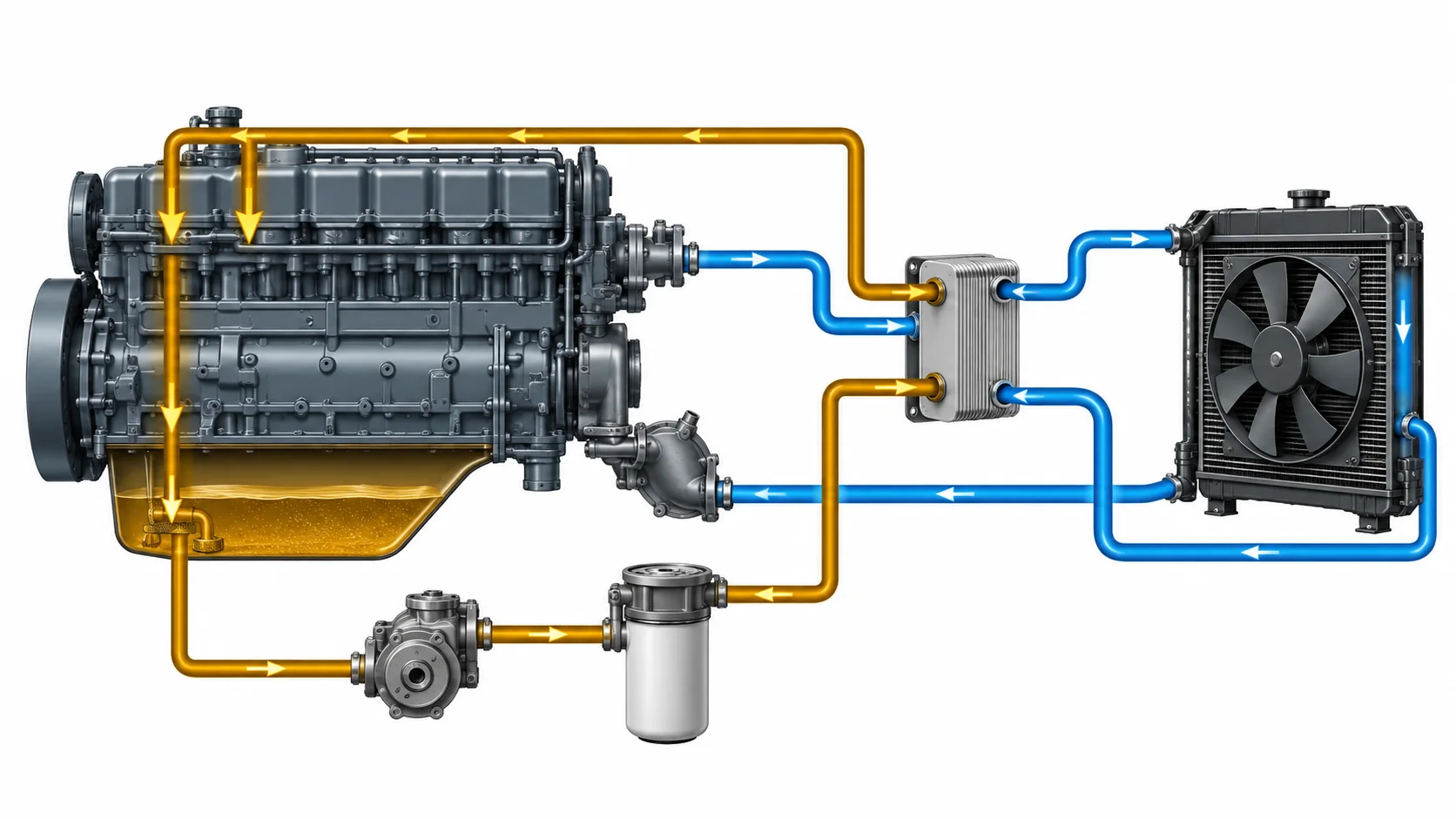
Diesel gensets commonly use oil-to-coolant or oil-to-air heat exchangers. An oil-to-coolant unit transfers oil heat to the engine coolant, often through a plate stack, shell-and-tube exchanger, or integrated housing. An oil-to-air cooler rejects heat directly to airflow and may be installed near the radiator or in a separate ducted path.
The oil cooler must be evaluated within the complete engine-lubrication and heat-rejection circuit.
The two designs are not interchangeable by capacity alone. A liquid-cooled unit depends on coolant temperature, flow, chemistry, and pressure. An air-cooled unit depends on ambient temperature, airflow, fan performance, duct sealing, and contamination. Specify both the hot and cold sides of the exchanger.
Heat Rejection Must Be Defined at a Condition
A heat-rejection figure is meaningful only when its operating condition is known. Useful inputs include oil inlet temperature, desired outlet temperature, oil flow, oil properties, cooling-air or coolant inlet temperature, secondary-side flow, altitude where relevant, and continuous versus standby duty.
Standby generator sets may run infrequently but must reach rated load when demanded. Prime-power and continuous-duty sets can accumulate heat for long periods. A cooler selected around a short unloaded test may be inadequate at sustained electrical load.
Do not convert rated electrical output directly into cooler size
Generator output provides context but does not establish how much heat enters the engine oil. Engine efficiency, operating point, lubrication architecture, coolant balance, and manufacturer calibration all matter. Use the engine or genset manufacturer's thermal data when available.
Pressure Drop Protects Oil Supply
The cooler adds resistance to the lubrication circuit. Excessive pressure drop can reduce the pressure or flow available to critical engine components, especially when oil is cold and viscous. A low-restriction core that does not reject enough heat is also unacceptable; both requirements must be met.
Record oil flow and allowable cooler pressure drop across the expected temperature range. Confirm whether the system has a cooler bypass, thermostatic valve, or pressure-relief arrangement. Do not remove or block a bypass to force all oil through a replacement cooler.
Opening, Bypass, and Warm-Up Control
Some systems route oil through the cooler continuously, while others use a thermostatic or pressure-responsive bypass. An integrated oil-filter housing may contain several passages and valves that are not visible from the outside. Replacing only the heat exchanger core does not correct a stuck bypass or damaged housing.
Document the complete oil path and consult verified service information. If oil temperature remains high after cooler replacement, investigate load, oil level and grade, coolant temperature, airflow, filter restriction, bypass operation, contamination, and sensor accuracy rather than assuming the new core is defective.
Size the Air Side or Coolant Side
For oil-to-air coolers
Provide maximum inlet-air temperature, available airflow, fan and shroud arrangement, permitted recirculation, altitude or density assumptions when relevant, and contamination conditions. Record whether the cooler sits ahead of or behind the radiator and charge-air cooler. Heat rejected by one core changes the inlet condition of the next.
Fin pitch should reflect the environment. Dense fins can improve clean-core heat transfer but may block rapidly in dusty, oily, or fibrous conditions. Cleaning access and protective grille design belong in the selection discussion.
For oil-to-coolant coolers
Provide coolant composition, inlet temperature, flow, system pressure, port arrangement, and allowable pressure drop. Material and seal compatibility matter. An internal failure can mix oil and coolant, so leak integrity and cross-contamination risk must be addressed.
Match Every Mechanical Interface
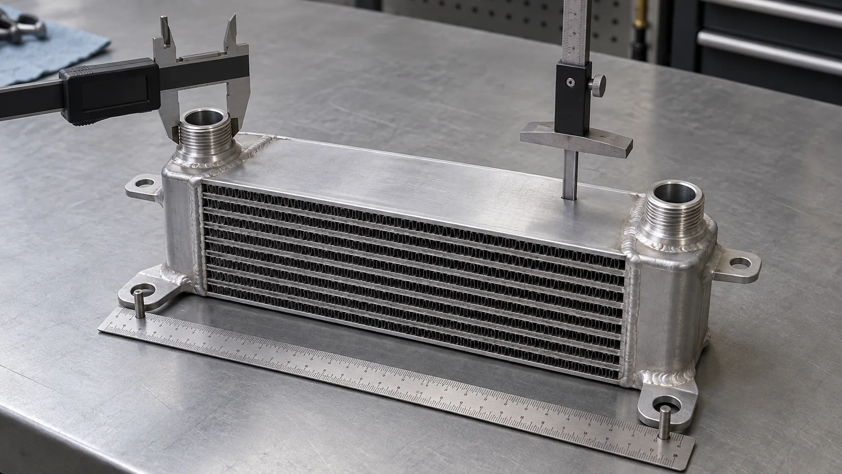
External length and width are only the start. Record core thickness, tank depth, port type and sealing method, thread or flange details, center distances, hose clearance, mounting-hole spacing, bracket offsets, installed orientation, and surrounding envelope.
Port seats, bracket offsets, mounting datums, and core depth should be measured from repeatable reference surfaces.
Photograph the original installed before removal, then photograph every face on a clean bench. Include a clear datum and units for each measurement. If a bracket is bent or a port is damaged, identify that condition so it is not copied as original geometry.
Evidence
Why it matters
Common mistake
Engine and cooler reference
Defines the catalog boundary
Using genset model alone when several engines are offered
Heat duty and temperatures
Defines required thermal performance
Matching by envelope only
Oil flow and pressure drop
Protects lubrication supply
Checking working pressure but not restriction
Cooling-side conditions
Defines available heat sink
Ignoring hot-air recirculation or coolant inlet temperature
Ports and mounting datums
Establishes physical interchange
Assuming a thread or bracket from appearance
Test and change records
Supports repeatable supply
Accepting an undocumented “tested” claim
Materials and Corrosion Environment
Cooler materials must be compatible with the oil, coolant if present, ambient contaminants, and connected metals. Coastal, humid, dusty, or chemically aggressive locations can increase corrosion exposure. Protective coatings must not obstruct heat-transfer surfaces or interfere with electrical grounding where that is part of the equipment design.
Do not approve a switch among aluminum, copper-brass, steel, or stainless construction without technical review. The change can affect weight, galvanic behavior, fatigue, repairability, and performance.
Testing and Quality Evidence
Ask the supplier to identify the test method, medium, pressure, duration, acceptance criteria, and traceability. A production leak test is not the same as proof, burst, thermal-performance, or pressure-pulsation validation. The required evidence should reflect the specified duty and purchasing risk.
The oil cooler pressure-test evidence guide provides a framework for separating these claims. Also define internal cleanliness, moisture control, capped-port protection, packaging, and handling. A clean cooler can be contaminated after testing if ports are left open.
Failure Evidence Should Guide the Replacement
Preserve the failed cooler long enough to document the cause. External fin blockage, oil leakage, coolant leakage, cracked brackets, vibration damage, corrosion, internal restriction, and contamination require different corrective actions. If the system problem is not corrected, the replacement may fail again.
Inspect hoses, supports, fan and shroud condition, radiator cleanliness, coolant operation, oil filter and bypass arrangement, and nearby vibration sources. A cooler that cracks near a port may be carrying hose load that should have been supported elsewhere.
A Generator Oil Cooler RFQ Checklist
Generator set, engine model, and original cooler reference;
engine-lube or auxiliary circuit identification;
oil type, flow, inlet temperature, and target outlet temperature;
heat rejection at the specified operating point;
maximum working pressure and allowable pressure drop;
air or coolant inlet conditions and flow;
standby, prime, or continuous duty and ambient range;
core envelope, ports, sealing faces, brackets, and mounting datums;
materials, coatings, cleanliness, and packaging requirements;
drawings, test records, sample approval, and change control;
annual demand and target U.S. market.
The broader Elecdura oil cooler range includes engine, transmission, and hydraulic applications. For an uncertain generator application, submit the original reference and a technical package before asking for a price comparison.
Frequently Asked Questions
Is a generator oil cooler the same as a transformer oil cooler?
No. This guide addresses diesel genset engine-lubrication cooling. Transformer-oil systems are a separate engineering category and should be specified independently.
Can I select a cooler from the generator's kW rating?
Not reliably. Use verified heat-rejection, flow, temperature, pressure-drop, cooling-side, and installation data for the actual engine and duty.
Can a larger cooler cause problems?
A larger envelope does not guarantee correct performance. It may change pressure drop, warm-up behavior, fan loading, airflow balance, mounting stress, and service clearance.
What if the original part number is unreadable?
Use the genset and engine identity, installed photographs, cooler construction, ports, mounting datums, dimensions, and operating data. Treat the result as an evidence-based match requiring sample confirmation.
Should the cooler be flushed after an engine failure?
Follow the engine manufacturer's approved contamination procedure. Some failure modes can leave debris in passages that cannot be verified clean by a casual rinse; replacement may be required.
Match Duty Before Dimensions
The correct generator oil cooler is the unit that satisfies the defined thermal duty without unacceptable restriction, fits the mechanical and fluid interfaces, survives the installation environment, and arrives with appropriate cleanliness and quality evidence. A similar-looking core is only a candidate.
For a wholesale enquiry, provide Elecdura with the original reference, complete genset and engine data, circuit identification, operating conditions, photographs, measurements, documentation requirements, and expected quantity. Keeping assumptions visible is faster and safer than discovering them after installation.