You are here:Home » Blog » Technical Guides » Oil Cooler Working, Proof, Burst, and Pulsation Pressure: What Buyers Should Request
Oil Cooler Working, Proof, Burst, and Pulsation Pressure: What Buyers Should Request
Views: 0 Author: Elecdura Publish Time: 2026-09-01 Origin: Site
Oil-cooler working pressure, proof pressure, burst pressure and pulsation endurance answer different questions and cannot be substituted for one another. A useful specification must identify the tested cooler, fluid or test medium, temperature, pressure waveform, hold time or cycle count, ramp rate, port and mounting condition, leakage limit, deformation limit and failure criterion. A single impressive pressure number without those conditions is not comparable supplier evidence.
For buyers of a wholesale oil cooler, the first task is to define the actual circuit. Engine lubrication, transmission, hydraulic, steering, compressor and industrial systems have different steady pressures, transients, temperatures, fluids and failure consequences. The cooler must meet the application requirement as a complete assembly, including core, tanks, brazed joints, fittings, seals, brackets and any bypass or thermostat.
Safety: pressure testing stores energy. Burst work requires trained personnel, rated fixtures, guarding, remote operation and a documented laboratory procedure. Hydrostatic methods are generally chosen to limit stored energy compared with compressed gas, but fluid injection, fragments and hose movement remain serious hazards.
Start with four clear definitions
Working pressure
Working pressure is the pressure range the manufacturer permits during normal service under stated conditions. It may be expressed as a maximum allowable working pressure, rated pressure or continuous pressure. The definition should state temperature and fluid because material strength, seal behavior and oil viscosity change with temperature.
Working pressure is not necessarily the most common gauge reading. A circuit can spend most of its life at a lower value yet experience relief-valve events, cold-start peaks or actuator shocks. The specified working envelope should account for the intended duty, while the system designer separately controls excursions and transients.
Proof pressure
A proof test applies a defined pressure above normal operation for a stated time to demonstrate integrity without rupture, unacceptable leakage or permanent deformation. It is a pass/fail verification, often performed on samples or production units depending on the control plan. A cooler that passes proof is expected to remain usable when the method defines a non-destructive test.
The proof ratio to working pressure is not universal. Product standards, customer specifications, materials and application risk determine it. Asking only “is it tested to 1.5 times?” can be misleading unless both the underlying working value and the complete procedure are known.
Burst pressure
Burst pressure is the pressure at which the assembly loses containment or meets a specified destructive-failure criterion during a controlled ramp. The result provides margin information and reveals the failure location. It is not an operating rating and should never be used as permission to run near that pressure.
A burst value is meaningful only with sample condition, medium, temperature, ramp rate, fixtures and definition of failure. First visible seepage, a sudden pressure drop, tank rupture and fitting pullout are different endpoints. Report the location and mode, not only the maximum gauge value.
Pulsation endurance
Pulsation testing repeatedly cycles pressure to evaluate fatigue. The upper and lower pressures, waveform, frequency, cycle count, fluid temperature and mounting determine severity. An assembly can survive a high one-time proof pressure yet crack after many lower cycles at a brazed joint or stress concentration.
Real circuits rarely produce ideal smooth sine waves. Pump ripple, gear changes, valve closure, relief operation and engine start create different shapes. A test waveform should represent the customer requirement or an applicable standard, including dwell and spike behavior where specified.
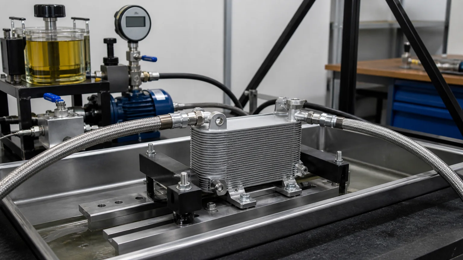
A controlled proof setup identifies the pressure source, medium, transducer, temperature, isolation, mounting, hold period and leakage observation method.
Why catalog pressure values are often not comparable
One supplier may publish maximum working pressure at room temperature, another a proof pressure at a defined oil temperature, and a third a minimum burst result from a prototype. The numbers can appear in the same table while describing different evidence. Translation can also turn “test pressure” into “working pressure.”
Core-only data is another trap. A plate-and-bar core may have a high pressure capability before tanks, threaded adapters, hoses or seals are attached. The purchased assembly fails at its weakest boundary. Request data for the exact part configuration, including the production joining process.
Temperature derating matters. Aluminum strength, polymer tank capability, elastomer sealing and brazed-joint behavior change as temperature rises. A room-temperature burst result does not automatically support hot hydraulic service. Cold conditions also matter because viscous oil increases pressure drop and can produce start-up peaks.
Setrab’s ProLine information illustrates that reputable manufacturers publish product-specific pressure and performance context. Buyers should still connect any published value to the exact series, part number and conditions. A value from one cooler family must not be copied into a specification for another construction.
Define the application pressure envelope first
Collect measured or validated circuit information before sending an RFQ. Include normal inlet and outlet pressure, maximum continuous pressure, relief setting, cold-start peak, transient magnitude and duration, pulsation source, oil temperature range, ambient range and duty cycle. State where pressure is measured because a cooler downstream of a valve can see a different condition from the pump outlet.
For an engine-oil circuit, start behavior and bypass strategy can dominate. Thick cold oil creates restriction, and the filter or cooler bypass may open. For a transmission cooler, line pressure and lubrication/cooling flow architecture depend on transmission design. For hydraulic return-line cooling, average pressure may be modest while shock or blocked-line events still matter. A cooler installed on a case-drain line has a particularly sensitive allowable backpressure.
Measure pressure with a transducer of suitable range and frequency response. A slow gauge can hide brief spikes, while an incorrectly installed high-frequency sensor can introduce its own resonance. Record sample rate, sensor location and calibration. If field data are unavailable, use the machine or system maker’s requirements rather than guessing from a similar vehicle.
Working pressure and pressure drop are different specifications
Pressure capability describes containment. Pressure drop describes the loss between inlet and outlet at a defined flow, fluid viscosity and temperature. A cooler can safely contain high static pressure yet impose too much restriction. Another can have low restriction but insufficient structural margin.
Request a pressure-drop curve, not one value without flow. The test fluid and temperature are essential because viscosity strongly affects loss. Port adapters and test hoses should be identified; otherwise their restriction may be included or excluded inconsistently. Evaluate cold-start conditions when relevant.
Cooling performance is a third dimension. Heat rejection depends on oil flow, air or coolant flow, inlet temperatures, ambient temperature and installation. A thick, highly reinforced core can meet pressure requirements but perform poorly if airflow is blocked. Select pressure capability, thermal capacity and acceptable restriction together.
How a proof test should be documented
A proof report should identify the part number, revision, sample or lot number, manufacture date, test date, operator and equipment. It should state whether the sample was new, conditioned, thermally aged, vibration-tested or previously pressure-cycled. Prior conditioning changes interpretation.
Describe the medium, fluid temperature, ambient temperature, filling and air-removal method, fixture orientation, port closures, mounting restraints, pressure ramp, target, tolerance, hold time and depressurization. Identify the pressure transducer range, accuracy and calibration status.
Define acceptance before the test: no external leakage, no pressure decay above the permitted amount after correcting for temperature, no permanent deformation beyond a measured limit, no fitting movement and no internal bypass failure where applicable. Visual inspection alone may miss small leaks; specify the detection method.
After depressurization, repeat dimensional or leak checks when the specification requires them. A unit that does not rupture can still be permanently swollen or have a weakened joint. Photographs before and after, plus the raw pressure-time trace, make the report auditable.
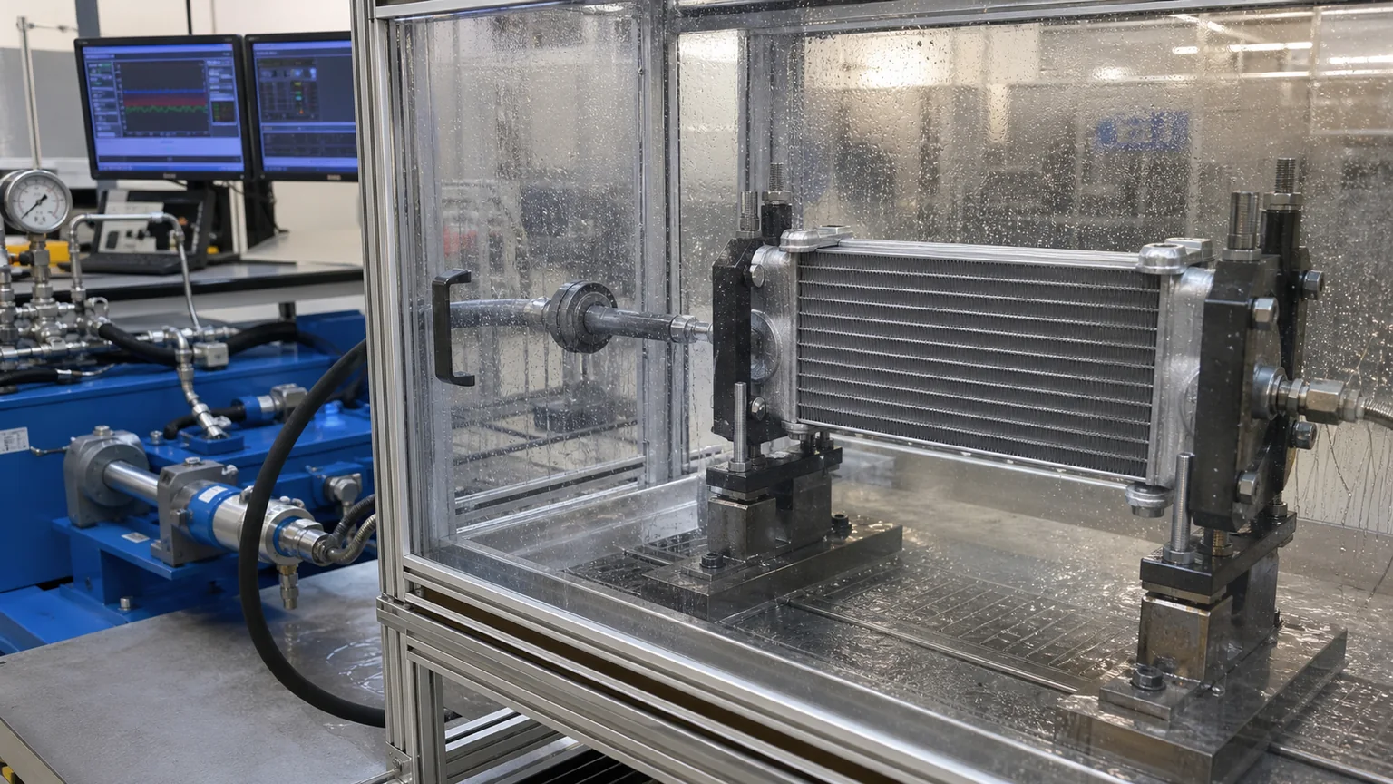
A burst test is destructive and remotely operated behind guarding. The result records pressure, ramp, temperature, medium and the first failure location.
Burst testing: use the failure, not just the headline number
A controlled burst test helps engineers understand margin and weak points. The assembly is completely filled with the specified liquid and air is removed as the procedure requires. It is mounted without artificial reinforcement, placed behind guarding, instrumented, then pressurized remotely at a defined rate until the failure criterion occurs.
Fixture design matters. A rigid block around a tank can support it and inflate the result. A heavy unsupported hose can load a fitting and lower the result. Threaded test plugs that engage more threads than the production connector change the boundary. The report should show the fixture and explain how normal installation constraints are represented.
Failure location drives corrective action. A core passage rupture can indicate wall or brazing limitations. Tank seam failure can point toward forming or welding. Adapter pullout can reveal thread engagement or joint weakness. A seal extrusion can show gap or material problems. A bracket tearing the tank during pressure growth may combine structural and mounting effects.
Minimum burst, average burst and individual values should not be confused. A small number of development samples does not establish production capability. Buyers should ask how minimum requirements are controlled through material certification, process monitoring, leak/proof testing and periodic validation.
Pulsation testing: the missing fatigue picture
A pulsation rig cycles the filled cooler between defined pressures. The trace should show actual upper and lower levels, rise and fall times, overshoot, frequency and dwell. Fluid temperature must be controlled or at least recorded because repeated compression and pumping can heat the medium.
Mounting should represent the vehicle or machine. Brackets that are fully rigid in a lab may remove vibration loads; soft hoses may remove connector forces. Some specifications combine pressure pulsation with temperature cycling, vibration or corrosion exposure because real failures result from interacting stresses.
Cycle count alone cannot compare tests. One million shallow cycles at room temperature may be less severe than fewer high-amplitude cycles at hot temperature with rapid ramps. Ask for the full waveform and failure criteria. A claim such as “pulsation tested” without them is marketing language, not engineering evidence.
Inspect at intervals only if the procedure permits interruption. Repeatedly disconnecting fixtures can change stress and sealing. Monitor pressure, leakage and temperature continuously, and record the cycle at which any anomaly begins. After completion, perform the specified leak, proof, dimensional and sectioning inspections.
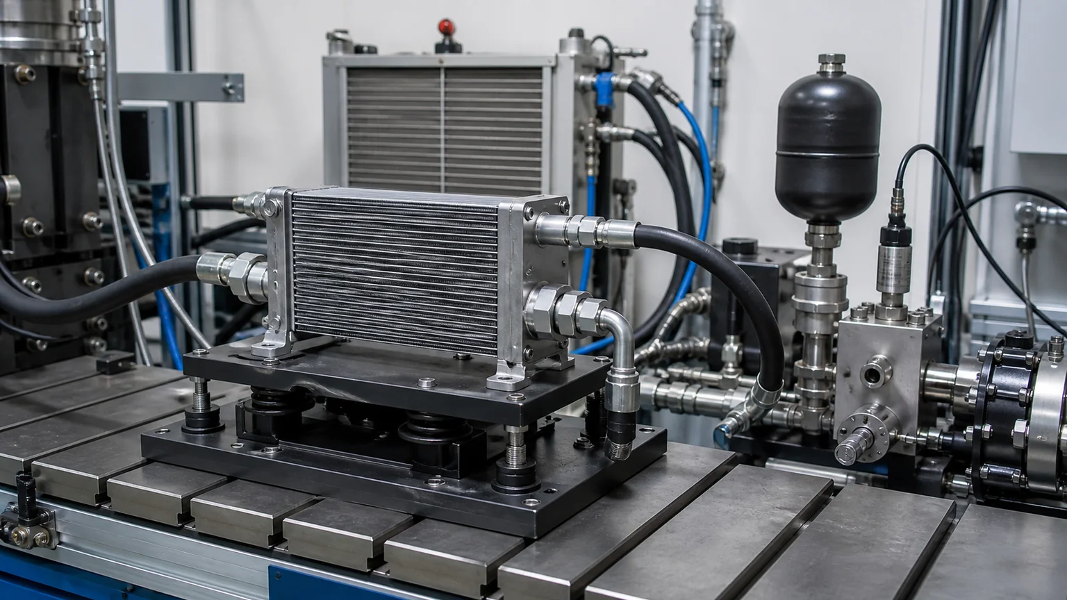
Pulsation evidence includes the real pressure-time waveform, controlled temperature, representative mounting, cycle count and post-test leak inspection.
Test medium and temperature can change the result
Water-based hydrostatic media are convenient and limit fire risk, but corrosion protection and complete drying may be required. Oil can better represent service viscosity and seal interaction, yet brings handling, fire and cleanup considerations. Water-glycol mixtures and dedicated test fluids may be specified. Compressed gas stores more energy and demands additional safeguards.
The medium affects leakage detection, compressibility, seal swelling and pressure drop. The procedure should state concentration, cleanliness and compatibility. A cooler intended for dielectric oil, refrigerant-oil mixture or aggressive fluid may require material-specific validation beyond pressure containment.
Temperature should represent the requirement or a defined standard condition. Heating only the external chamber while the internal fluid remains cool is not equivalent to hot-fluid testing. Record both where relevant. Stabilization time and thermal gradients can affect seals and measurement.
Production leak tests are not automatically proof tests
Many factories test every cooler for leakage using air under water, pressure decay, differential pressure, helium or another method. These controls can efficiently detect manufacturing defects. Their pressure may be below, at or above working pressure depending on the method and safety design. The term “100% pressure tested” does not reveal which function was tested.
A leak test focuses on escaping medium above a sensitivity threshold. A proof test demonstrates structural integrity at a defined load. A burst test finds destructive margin. A pulsation test evaluates fatigue. A supplier may legitimately use all four at different frequencies: every-unit leak testing, sampled proof testing, periodic burst testing and development or validation pulsation testing.
Ask how the leak threshold is expressed and correlated. Pressure-decay limits depend on internal volume, stabilization time and temperature. Bubble observation depends on dwell and operator visibility. Helium methods require calibrated leak standards and control of background concentration.
Special components that alter the pressure boundary
Bypass valves and thermostats
A bypass can protect the circuit from excessive restriction or control warm-up. Its opening pressure, flow direction and leakage become part of the assembly behavior. A core pressure test with the bypass removed does not validate the complete oil cooler assembly.
Hoses, manifolds and adapters
Crimped hoses and cast manifolds can be the first failure point. Test the configuration that will be supplied or qualify each boundary with a controlled interface specification. Port standards that appear similar may have different threads or sealing seats.
Polymer tanks and seals
Time, temperature, fluid exposure and clamp relaxation affect polymers and elastomers. New-part burst data should be supplemented with aging or endurance evidence when the application requires it. Verify fluid compatibility and temperature range.
Mounting brackets
Pressure can make a cooler grow or bow. A bracket that restrains expansion may concentrate stress. Vehicle vibration adds load around welds and brazed attachments. Pressure validation should use representative mounting and be supported by vibration requirements where needed.
Supplier evidence matrix
Evidence
Question answered
Conditions that must accompany it
Working-pressure rating
Where may the cooler operate continuously?
Part number, fluid, temperature, duty, derating and applicable standard
Proof report
Did the sample withstand a defined non-destructive overload?
Pressure, hold, medium, temperature, acceptance, sample state and trace
Burst report
What destructive margin and failure mode were observed?
Ramp, medium, temperature, fixture, sample values, minimum and failure location
Pulsation report
Can the assembly resist repeated pressure fatigue?
Upper/lower pressure, waveform, frequency, cycles, temperature, mounting and inspections
Leak-test control plan
How are production leaks detected?
Method, pressure, threshold, stabilization, frequency and gauge calibration
Pressure-drop curve
Will the cooler restrict the circuit?
Flow, fluid, viscosity/temperature, ports and uncertainty
Thermal performance map
Can it reject the required heat?
Oil/air or coolant flows, inlet temperatures, ambient and installation
RFQ wording that produces comparable answers
Instead of asking “What is your burst pressure?”, specify the application envelope and request completed fields. Example: identify the cooler part or drawing revision; fluid and temperature range; maximum continuous pressure; transient trace; required proof method; minimum burst criterion; pulsation waveform and cycle count; pressure-drop limits; thermal duty; ports; mounting; corrosion requirement; annual volume and traceability.
Ask suppliers to state deviations explicitly and attach unedited pressure-time data. Require the laboratory, equipment and calibration status, sample quantity, individual results and failure photographs. If a test follows a standard, request the edition and clauses used. “According to an equivalent method” should include a difference analysis.
For hydraulic equipment, use the machine and circuit details when evaluating a hydraulic oil cooler. For lubrication circuits, compare with the correct engine oil cooler construction rather than assuming their pressure and flow requirements are identical.
Red flags in a pressure claim
One pressure number is shown without calling it working, proof or burst.
The value belongs to a material or core series, not the supplied assembly.
Temperature and test medium are absent.
A single prototype result is presented as a guaranteed minimum.
There is no pressure-time trace, equipment record or sample identification.
Pulsation is described only by cycle count.
Fixtures visibly reinforce tanks or use non-production adapters.
Leakage, deformation and failure criteria are undefined.
Room-temperature data are applied to hot service without derating.
Burst pressure is used as the recommended system operating pressure.
Pressure capacity is presented as proof of low restriction or high cooling capacity.
Buyer approval checklist
The real continuous, peak and pulsating circuit pressures are defined at the cooler location.
Fluid, temperatures, flow, viscosity and duty cycle are stated.
The working-pressure rating applies to the exact complete assembly.
Proof, burst and pulsation requirements have distinct procedures and acceptance criteria.
Tests use representative ports, seals, brackets and mounting.
Reports identify sample, revision, conditioning, equipment and calibration.
Pressure traces and individual results are available.
Production leak testing is defined separately.
Pressure-drop and thermal-performance evidence also meets the system requirement.
Changes to materials, brazing, welding, tanks, fittings or seals require notification and revalidation rules.
Key conclusion: pressure evidence becomes useful only when the definition and test conditions travel with the number. Working pressure sets the service envelope, proof checks non-destructive integrity, burst reveals destructive margin, and pulsation evaluates fatigue. Buyers who specify the circuit, waveform, temperature, medium and acceptance criteria can compare suppliers on evidence instead of headline pressure.