English
Views: 0 Author: Elecdura Publish Time: 2026-08-07 Origin: Elecdura
When a blower motor only works on high speed, the failed part depends on how the vehicle controls blower speed. A manual HVAC system often routes the lower speeds through a resistor pack and gives the highest speed a low-resistance bypass. An automatic climate-control system may use a transistorized power module that receives a pulse-width-modulated or other control signal. A missing low-speed command, overheated connector, poor ground, worn motor, or obstructed airflow can produce the same driver complaint.
The symptom makes a resistor failure likely on many manual systems, but it does not authorize blind replacement. A new resistor can fail again if an aging blower draws excessive current or if leaves, a restricted cabin filter, or incorrect installation prevents cooling air from reaching the resistor. Begin with the circuit topology, then measure voltage, voltage drop, and current. Elecdura's automotive parts range can support replacement sourcing only after the control type and damaged boundary are known.
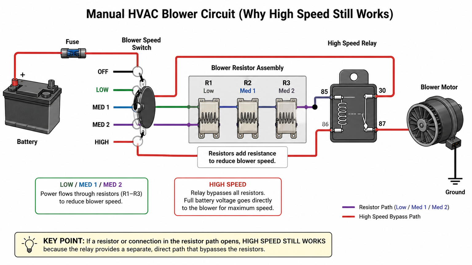
In a stepped manual circuit, electrical resistance converts part of the supply energy into heat so the motor receives less voltage on lower settings. The resistor pack is usually mounted in the HVAC air stream to remove that heat. At the highest setting, a relay or switch path may bypass most or all of the resistor elements. If a thermal fuse or resistor coil opens, the bypass can still power the motor.
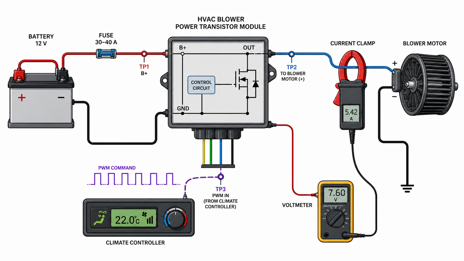
In an electronic system, the power module rapidly controls current or varies the ground path instead of selecting wire coils. Some systems place the module on the power side, others on the ground side, and some communicate through a data network. "Blower resistor" is therefore not a safe catalog name for every electronic controller.
System | How speed changes | Why high may still work | Likely test target |
|---|---|---|---|
Manual resistor pack | Switch selects resistor paths | High-speed bypass avoids open resistor or thermal fuse | Resistor continuity, connector heat, switch output |
Manual circuit with relay | Resistors for low speeds, relay for high | High relay has a separate current path | Resistor feed and selector contacts |
Automatic HVAC power module | Transistor controls motor current | Module may fail in one command range or default state | Command signal, power, ground, module output |
Network-controlled blower | HVAC controller sends digital request | Fallback behavior varies by design | Codes, network data, module supplies, commanded speed |
Cycle the ignition and test each blower setting with the engine running if the service procedure requires it. Record whether the motor is completely off, turns slowly, starts after a delay, changes with bumps, or works only when the control is held between positions. Test floor, panel, defrost, recirculation, and automatic modes. A system may intentionally command a different speed during defrost, battery protection, engine stop-start, or climate-control self-tests.
A hum, intermittent start, squeal, or response after tapping the housing suggests worn brushes, dry bearings, debris, or a tight wheel. Tapping is not a repair and can damage the housing. If the motor needs the higher voltage or duty cycle to overcome friction, the symptom can mimic a resistor fault even though the lower-speed circuit is intact.
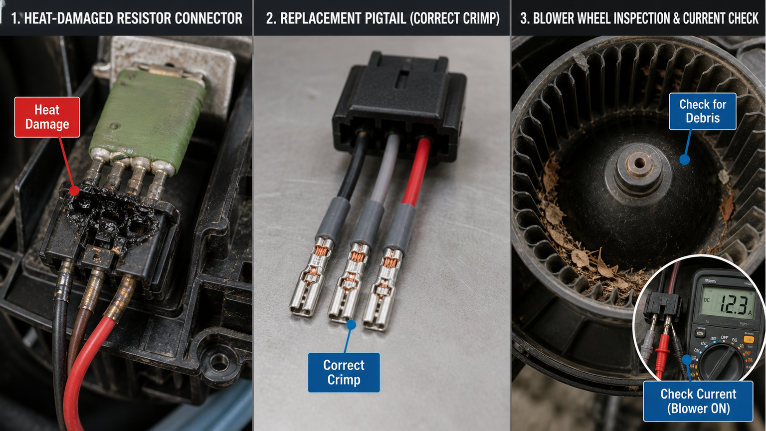
Check the cabin filter, inlet screen, evaporator face where accessible, blower wheel, and duct for obstruction. The resistor or power module depends on airflow, and the motor works harder when the wheel is packed with debris or rubbing. Water entry can corrode the connector and increase bearing drag. Correct the airflow or water-management cause as part of the repair.
Do not assume the same trim level uses the same HVAC controller. Record the VIN, market, manual or automatic climate control, number of zones, rear HVAC equipment, left- or right-hand drive, and production date. Locate the fuse, blower relay, control head, resistor or power module, motor, splice points, and ground. Identify whether the control head switches power, switches ground, commands a relay, outputs a duty-cycle signal, or sends a network message.
A resistor pack often has multiple terminals representing several speed paths and a common feed or output. Wire gauge may be heavier on the high-current path. The unit usually protrudes into the air case. Do not judge the pin function from position; use the diagram. Thermal fuses are safety devices and should not be bridged.
A transistor module may have a heavy power terminal, heavy motor terminal, ground, and one or more small command or communication terminals. It may include a large heat sink in the duct. Resistance across power terminals is rarely a complete test because semiconductor behavior depends on polarity, command, load, and internal protection.
Automatic systems may store codes for the blower module, control signal, supply voltage, temperature sensors, or communication. Compare requested blower speed with actual or inferred speed if supported. A control head that never requests low speed is a different fault from a power module that receives the request but produces no output.
A visual fuse inspection can miss a cracked element or poor terminal. Check voltage on both sides under the operating condition. For a relay, confirm coil command, coil ground, input power, and switched output. Do not substitute a relay unless pin layout, coil suppression, contact rating, and control design are confirmed.
With the blower operating, measure voltage drop from the battery positive terminal to the motor or module supply and from the motor or module ground back to battery negative. A high-resistance terminal may look normal with the circuit disconnected but lose voltage under current. Follow manufacturer limits and protect meter leads from the fan wheel.
If the module varies the ground side, the motor may have near-battery voltage on its positive terminal at every speed while the controlled ground voltage changes. Measuring only the power side would falsely suggest the circuit is healthy. The diagram determines the reference point for every measurement.
Disconnect power and follow the specified continuity or resistance checks. An open path that corresponds to the missing lower speeds supports a failed resistor or thermal fuse. Also inspect the terminal tension, discoloration, melted cavity, and wire insulation. Resistance values can be very low, so subtract lead resistance and do not overinterpret an uncalibrated handheld reading.
Use a meter or oscilloscope appropriate to the signal. Observe whether duty cycle, voltage, or communication request changes as the control head moves from low to high. A stable supply and ground with a correct changing command but no proportional output supports a module fault. A missing command requires diagnosis upstream.
Use a current clamp or the approved series method and compare the stabilized current at the specified voltage with service information. Check startup current, bearing noise, wheel contact, and speed stability. Excess current heats the resistor, module, switch, relay, and connector. Replacing only the overheated controller can create a repeat failure.
Test result | Most useful next step | Do not conclude yet |
|---|---|---|
High works; resistor path is open | Inspect airflow, connector, and motor current before replacement | That the resistor failed without an external cause |
Correct PWM command; stable supplies; no module output | Confirm motor/load, then replace matched module | That every vehicle uses the same signal polarity |
Voltage collapses at connector under load | Locate terminal or wire voltage drop | That the motor is defective because it runs slowly |
Motor current exceeds specification | Inspect wheel and airflow; replace motor if mechanically/electrically faulty | That a new resistor alone will last |
No low-speed request from control head | Check inputs, codes, controller power, and logic | That the power module ignored a command it never received |
Heat at a blower connector can come from high motor current, low terminal contact force, corrosion, incomplete engagement, poor crimping, undersized replacement wire, or repeated arcing. Once heat relaxes the terminal and deforms the plastic cavity, cleaning the blade is often insufficient. The repair may require the resistor or module, a specified connector pigtail, and the motor or airflow correction that caused the load.
Check the component blade and harness terminal for pitting, oxidation, discoloration, looseness, and displaced seals. A new module plugged into a heat-damaged female terminal can develop the same voltage drop. Use the correct terminal tool and splice method; twisting wires and covering them with tape is not a durable high-current repair.
Use the specified conductor size and temperature rating. Stagger splices when instructed, keep them away from water paths and sharp edges, and restore loom support. A pigtail color may not match the vehicle harness; map each circuit by terminal function, not color alone.
This pattern may be normal load management, or it may reveal marginal supply voltage. Compare the blower request, battery voltage, charging voltage, and voltage drop with the key on and with the engine running. Do not treat an alternator-dependent improvement as proof of a stronger motor. The higher system voltage may simply overcome resistance at a damaged connector. Broader on-highway electrical loads must be assessed under the specified operating condition.
Temperature-sensitive operation can come from a cracked resistor element, semiconductor protection, relaxed terminal, control-head contact, or tight motor bearing. Measure the circuit during the failure, because an open connection may close as it cools. Infrared temperature evidence can help locate a hot joint, but emissivity, airflow, and access affect the reading. Physical discoloration plus loaded voltage drop is stronger evidence than temperature alone.
This is not the classic high-only electrical symptom. Inspect the cabin filter, blower-wheel attachment and direction, recirculation door, evaporator restriction, and disconnected duct. A wheel fitted backward or slipping on the shaft can make noise without moving the expected air. Cooling components such as an AC condenser affect refrigerant heat rejection, but they do not explain why the cabin fan produces weak volume at the vents.
A shorted power transistor can leave the motor powered, while retained accessory power, an after-blow drying strategy, a stuck relay, or a control command may be intentional. Scan the HVAC system and observe the module command before disconnecting components. If current draw continues beyond the specified time, isolate the relay or module path according to the diagram. This condition should not be merged with the lower-speeds-missing diagnosis merely because the same power module is involved.
Multi-zone vehicles can have separate motors, resistors or modules, fuses, grounds, and control requests. Identify the physical location and connector before ordering. A front unit from a broad aftermarket range may look similar but use a different mounting flange or control signal. For fleet and bus applications, rear duct length, inlet restriction, and service accessibility also alter the thermal environment of the controller.
The cabin blower moves air across the evaporator and heater core; it does not pump refrigerant or engine coolant. If airflow is correct but air is warm, continue into refrigerant, blend-door, or coolant diagnosis. Elecdura's AC compressor range, electric compressor range, and engine cooling parts represent different system boundaries. Linking the complaint to the correct boundary avoids replacing a resistor for a temperature problem or replacing a compressor for an airflow problem.
For wholesale planning, keep a separate validation sheet for each boundary. The blower-control sheet should contain the control topology, connector and mounting data, current test, airflow condition, and pigtail requirement. Refrigerant components require their own port, refrigerant, oil, control-valve, and application data. Use the catalog center to organize candidate references, then confirm exceptions before a bulk order.
Match the exact control type, OE number, connector keying, pin count, mounting flange, heat-sink dimensions, screw centers, and HVAC application. Manual and automatic climate-control parts can fit the same opening but operate differently. Rear HVAC may use another module. A resistor supplied with an adapter harness should not be assumed compatible without an authoritative application reference.
OE number from the original resistor, module, motor, and connector where available;
vehicle, year, market, HVAC control type, and front or rear location;
clear connector-face, label, heat-sink, and mounting photos;
pin count and keying, not guessed wire colors;
diagnostic result, motor current, and connector condition;
whether a pigtail, seals, screws, or mounting gasket is required;
quantity, destination, packaging, and sample validation plan.
Elecdura's aftermarket sourcing program and catalog resources can support range planning. For mixed orders, keep belt-driven AC compressors, electric AC compressors, and AC condensers as separate lines with their own matching data; they do not confirm blower control fitment.
Verify terminal alignment, connector retention, mounting flatness, heat-sink cleanliness, component marking, and functional output on an appropriate fixture. Protect exposed pins and heat-sink fins from bending. Motors require protection for the wheel and shaft so a correct electrical part does not arrive with imbalance or end-play damage. The on-highway application range may include many HVAC variants, so labels and lot traceability are essential.
Confirm that the vehicle uses a resistor pack, then test the lower-speed paths, connector, switch output, power and ground. Automatic climate control may use an electronic module instead.
A tight bearing, rubbing wheel, debris, water damage, or electrical winding fault can raise current. Restricted duct airflow can also overheat the controller. Measure current and inspect airflow before closing the repair.
Vibration may temporarily move worn motor brushes, a loose connector, a relay contact, or a cracked solder joint. Locate the circuit fault; repeated impact can damage trim and does not establish which part failed.
A temporary bypass outside the service procedure can overload wiring or eliminate thermal protection. Use manufacturer-approved tests and restore the designed circuit.
Provide the OE reference, vehicle and HVAC configuration, module or resistor label, connector face and pin count, mounting and heat-sink views, motor current result, damaged pigtail details, required accessories, and quantity through Elecdura's contact page.
When the blower operates only on high, first identify whether speed is controlled by resistors, a relay bypass, a transistor module, or a networked controller. Then verify the low-speed request, loaded power and ground, controller output, connector voltage drop, motor current, and cooling airflow. Replace the failed boundary and the cause of overheating together. That sequence turns a familiar symptom into a repeatable repair and provides the exact electrical and physical data required for a reliable wholesale quotation.