
English
Views: 0 Author: Site Editor Publish Time: 2026-09-23 Origin: Site
A passenger-train oil cooler must be selected as part of a thermal and mechanical system, not as a rectangular core with similar ports. The correct unit depends on what fluid is being cooled, where it is installed, the heat load and allowable pressure drop, airflow or coolant conditions, mounting loads, vibration exposure, contamination, service access, and the evidence required by the rail operator or equipment owner.
This guide is written for U.S. rail-parts distributors, maintenance organizations, fleet buyers, and sourcing teams evaluating replacement or custom oil coolers. It explains the information needed before a supplier can make a responsible recommendation. It does not claim that a generic cooler is approved for any particular rail vehicle.
“Train oil cooler” can describe several different duties. A cooler may serve diesel-engine lubricating oil, transmission or gearbox oil, hydraulic oil, compressor lubrication, or another auxiliary circuit. Electric multiple units can have different thermal architectures from diesel multiple units, and a passenger railcar is not automatically equivalent to a locomotive.
The RFQ should name the equipment and circuit before dimensions are discussed. Record the rail vehicle or powerpack model, equipment manufacturer, assembly number, original cooler reference, fluid type, and location. If the cooler is part of a combined module, document every connected circuit.
An air-cooled oil cooler transfers heat from oil to ambient or forced air through a finned core. Performance depends strongly on airflow, inlet-air temperature, fin condition, shrouding, and recirculation. It may be mounted underfloor, on a roof module, in an engine bay, or within a packaged cooling group.
A liquid-cooled oil cooler transfers heat to another coolant circuit. Plate-type or shell-and-tube arrangements can fit where direct airflow is limited, but the secondary circuit's temperature, flow, chemistry, and pressure become part of the specification. A supplier needs data for both sides of the exchanger.
Design question |
Air-cooled unit |
Liquid-cooled unit |
|---|---|---|
Heat sink |
Ambient or ducted airflow |
Engine or dedicated coolant circuit |
Critical external condition |
Air temperature, flow, debris and recirculation |
Coolant temperature, flow and chemistry |
Common packaging issue |
Shroud, fan, grille and fin clearance |
Port routing, coolant connections and service isolation |
Inspection focus |
Fin blockage, impact damage and air seals |
Internal leakage, fouling and cross-contamination |
Overall dimensions do not establish cooling capacity. The required heat rejection is influenced by oil flow, oil properties, inlet and target outlet temperatures, ambient or coolant inlet temperature, duty cycle, and the equipment's operating margin. Peak load and continuous load should not be confused.
Provide measured or manufacturer-specified operating points whenever possible. If a complete thermal duty is unavailable, state which values are known and which remain assumptions. Do not ask a supplier to “match the capacity” from a photograph.
A cooler can reject heat yet impose excessive restriction. Oil viscosity changes with temperature, and cold-start conditions may be more demanding than a warm steady-state test. Record allowable pressure drop across the cooler and the operating temperature range. Confirm whether a bypass or pressure-relief path exists elsewhere in the circuit.
Passenger rail equipment experiences vibration, shock, weather, ballast dust, water spray, temperature cycling, and repeated service access. A replacement core must fit the physical envelope while preserving clearances, airflow, drain paths, and maintainability.
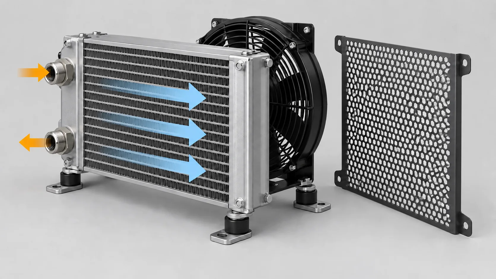
This generic product-function illustration shows the features to verify without implying a specific railcar installation.
Photograph brackets, isolators, locating features, support frames, and any flexible connections. Measure hole centers from repeatable datum surfaces and record bracket thickness, offset, and installed orientation. Note whether the cooler carries hose loads or whether hoses are separately supported.
A rigidly mounted replacement can transfer vibration into end tanks or tube joints. Conversely, an overly soft mounting arrangement can allow contact with surrounding structure. Preserve the intended mounting concept unless an approved engineering change states otherwise.
For air-cooled units, document fan direction, ducting, shrouds, seals, grille condition, and the location of other heat exchangers. Air can bypass a core through missing foam or panel gaps. A clean new cooler will not perform as intended if hot discharge air recirculates to its inlet.
Underfloor units may collect dust, fibers, oil mist, insects, or road debris. Fin pitch and cleaning access affect serviceability. Do not automatically choose the densest fin pack; it may offer strong clean-core performance but foul quickly in the actual duty.
Record port type, nominal size, thread form, sealing method, center spacing, clock position, and clearance for fittings. Photograph each port square-on and from the side. A thread that appears to engage is not proof of the correct standard or sealing seat.
Confirm compatibility among the oil, cooler materials, seals, hoses, and cleaning agents. Aluminum, copper-brass, steel, and stainless constructions each have different manufacturing and service considerations. Material substitutions require engineering review rather than a price-only decision.
If the original unit has failed internally, determine whether debris or cross-contamination can remain in connected components. The correct response depends on the failure mode and the operator's approved maintenance procedure.
The visible core is only one part of the assembly. Inspect end-tank attachment, tube-to-header joints, weld continuity, brazed areas, port reinforcement, bracket transitions, drain features, protective coatings, and fin support. Look for sharp edges or unprotected surfaces that could damage adjacent hoses.
Ask for a controlled drawing identifying overall envelope, core dimensions, mounting datums, ports, materials, mass, and revision. When a sample is approved, retain photographs and measured characteristics as part of the purchasing record. This helps distinguish an intentional engineering revision from uncontrolled drift.
Test requirements must be tied to the cooler's specified working conditions and approved procedure. A statement that a unit was “pressure tested” is incomplete without the test medium, pressure, duration, acceptance criterion, temperature if relevant, and record traceability. Proof, burst, fatigue, and leak tests answer different questions.
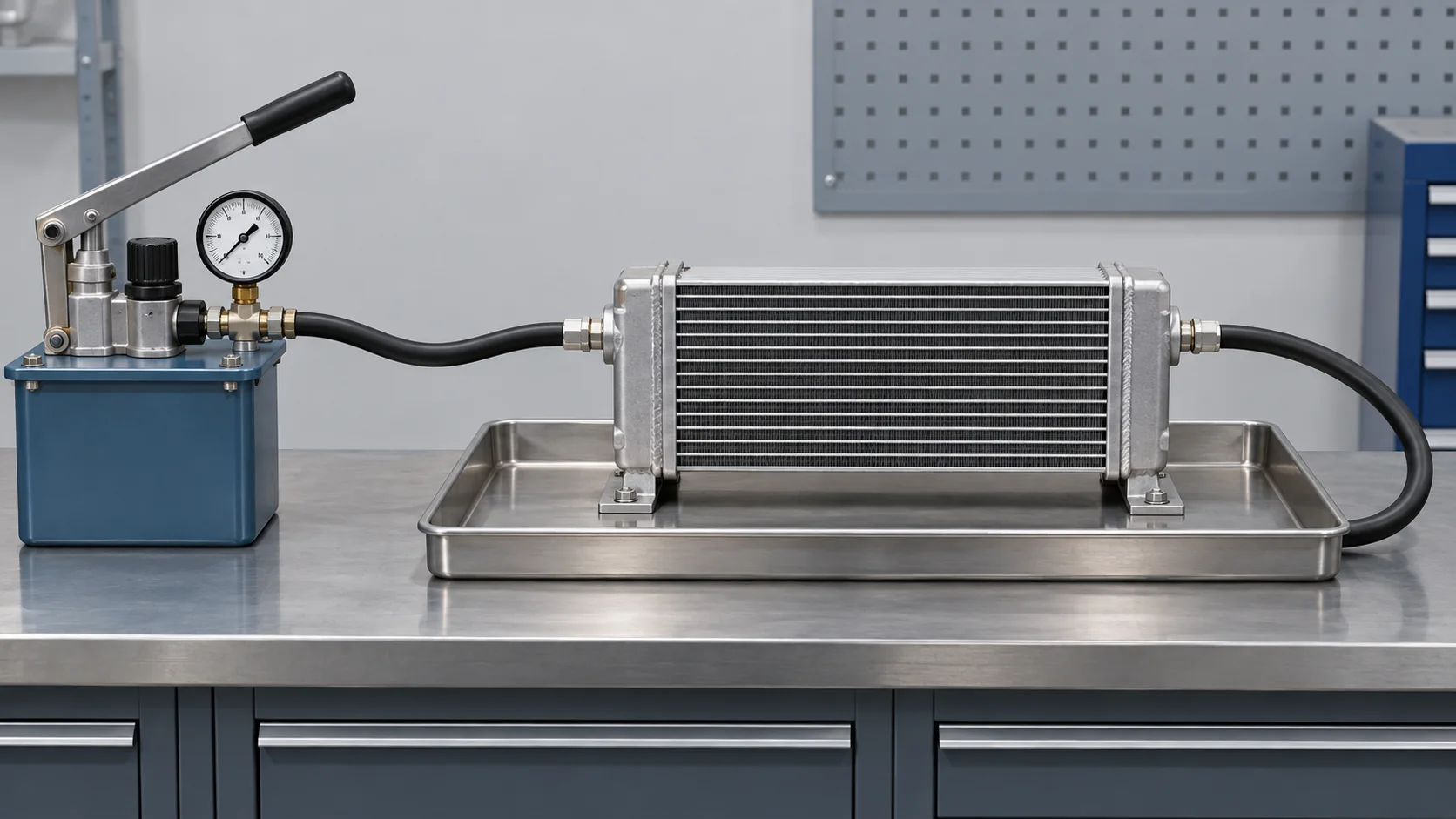
Useful test evidence identifies the method, conditions, acceptance criteria, and traceable result—not merely a pass label.
The oil-cooler pressure-test evidence guide explains how working, proof, burst, and pulsation claims should be separated. Buyers should also define internal cleanliness and port protection. Residual particles, moisture, or uncapped openings can damage downstream equipment even when the cooler itself does not leak.
A direct replacement is appropriate only when the part reference and interfaces are established. Repair may be considered under the operator's approved process when the failure, material, and service condition permit it. Custom reproduction may be needed for obsolete equipment, but it requires a controlled technical package and validation plan.
Do not use a repaired or reverse-engineered cooler in safety- or reliability-critical service simply because it passes a single static leak check. The acceptance process must reflect the operator's requirements, duty, and applicable documentation.
Rail vehicle, powerpack, and equipment model;
original manufacturer and part reference;
oil circuit and fluid specification;
oil flow, inlet temperature, target outlet temperature, and heat rejection;
maximum working pressure and allowable pressure drop;
air or secondary-coolant inlet conditions and flow;
overall envelope, core size, port details, and mounting datums;
vibration isolation, orientation, airflow direction, and service access;
materials, coating, cleanliness, and port protection;
required inspections, test records, drawing revision, and sample process;
annual quantity, delivery packaging, and target U.S. market.
Elecdura's oil cooler product category provides the broader engine, transmission, and hydraulic cooler context. For custom or uncertain applications, send a complete evidence package rather than relying on a product photo.
Two cores with the same envelope can have different tube geometry, fin design, circuit arrangement, and pressure drop. Dimensions establish fit, not thermal equivalence.
Passenger railcars, locomotives, and auxiliary power units can have different circuits and duty. State the equipment rather than using a broad market label.
A supplier cannot correct blocked grilles, reversed fan flow, missing seals, or hot-air recirculation with the core alone.
A change in alloy, wall thickness, coating, seal, or joining process may affect corrosion, fatigue, or compatibility. Require controlled change communication.
Not without engineering evidence. Rail duty, capacity, pressure drop, vibration, environment, mounting, documentation, and operator requirements must all be satisfied.
No general equivalence should be assumed. Identify the specific vehicle, equipment, fluid circuit, and original assembly.
Engine power may provide context, but it does not replace heat-rejection, flow, temperature, pressure-drop, and installation data.
Provide the installed location, every side of the removed unit, labels and references, ports, mounting points, brackets, damaged area, surrounding airflow hardware, and scale-referenced dimensions.
Verify drawing revision, envelope, ports, mounting, materials, workmanship, cleanliness, protection, test records, and performance under an approved validation plan.
A reliable passenger-train oil cooler project begins with the circuit and operating duty, then moves through pressure drop, installation, materials, interfaces, testing, and change control. That sequence gives a supplier enough information to identify a valid replacement—or to explain why a custom engineering review is required.
For a wholesale or custom enquiry, send Elecdura the original reference, rail equipment data, operating conditions, drawing or measured interfaces, clear photographs, required documentation, and expected quantity. Any unresolved assumption should remain visible until the sample and validation process closes it.


