English
Views: 0 Author: Site Editor Publish Time: 2026-08-25 Origin: Site
Predictive cooling maintenance does not begin with an alarm threshold. It begins with a repeatable baseline: the same vehicle or equipment family, similar ambient temperature, load, speed, cooling-fan or compressor command, coolant condition, and measurement locations. Current, pressure, and temperature become useful only when the fleet can explain what operating condition produced them. A single high value may reflect a hot day or heavy duty; a gradual change under comparable conditions is more likely to justify inspection.
The objective is not to replace parts before they fail. It is to detect lost airflow, rising electrical load, reduced heat-transfer efficiency, refrigerant-control drift, coolant-flow problems, or intermittent control faults early enough to plan a controlled inspection. The work order should still identify a failed boundary before a fan, condenser, radiator, compressor, pump, thermostat, or control module is ordered.
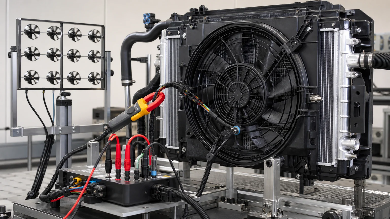
Predictive maintenance begins with repeatable measurements under comparable operating conditions.
Signal family | Useful examples | What a trend may reveal | What must be normalized |
|---|---|---|---|
Electrical current and voltage | Cooling fan current, pump current, compressor power, fan-control voltage drop | Bearing drag, blockage load, weak supply, connector heating, motor wear, control mismatch | Commanded speed, system voltage, ambient, airflow resistance and component variant |
Pressure | Refrigerant high/low side; coolant pressure where designed; differential pressure across a defined circuit | Each belongs to a different physical boundary: refrigerant state, coolant-circuit state, or flow resistance | Applicable fluid, ambient, command, airflow, load, measurement locations and sensor calibration |
Temperature | Coolant inlet/outlet, refrigerant line temperatures, core face temperature, battery/engine/electronics temperatures | Reduced heat transfer, weak flow, blocked airflow, control drift, thermostat/valve behavior | Load, flow, ambient, vehicle speed, measurement location, warm-up state and sensor offset |
No signal should be interpreted alone. A fan’s rising current is more meaningful when commanded speed and system voltage remain similar and airflow falls. High refrigerant pressure is more useful when compressor command is known and condenser airflow has been measured. A changing coolant temperature difference needs pump or engine speed, heat load, thermostat/valve state, and ambient context.
Separate vehicles by model, powertrain, cooling package, software or control variant, fan assembly, compressor type, and duty cycle. A city bus idling with frequent door openings should not share one temperature threshold with a highway truck. A vehicle with a variable-speed brushless fan should not be compared directly with a two-speed relay-controlled motor. If the fleet has mixed aftermarket and original parts, record that fact because electrical and thermal characteristics may differ.
Collect data at repeatable moments: cold start, warmed idle, defined engine or motor load, A/C maximum request, stationary fan test, steady road speed, charging-related thermal monitoring where applicable, or post-route inspection. Record ambient temperature and humidity where relevant, vehicle speed, load, fan/compressor/pump command, coolant and refrigerant state, and any active faults. A trend built from uncontrolled snapshots will mostly describe changing weather and duty.
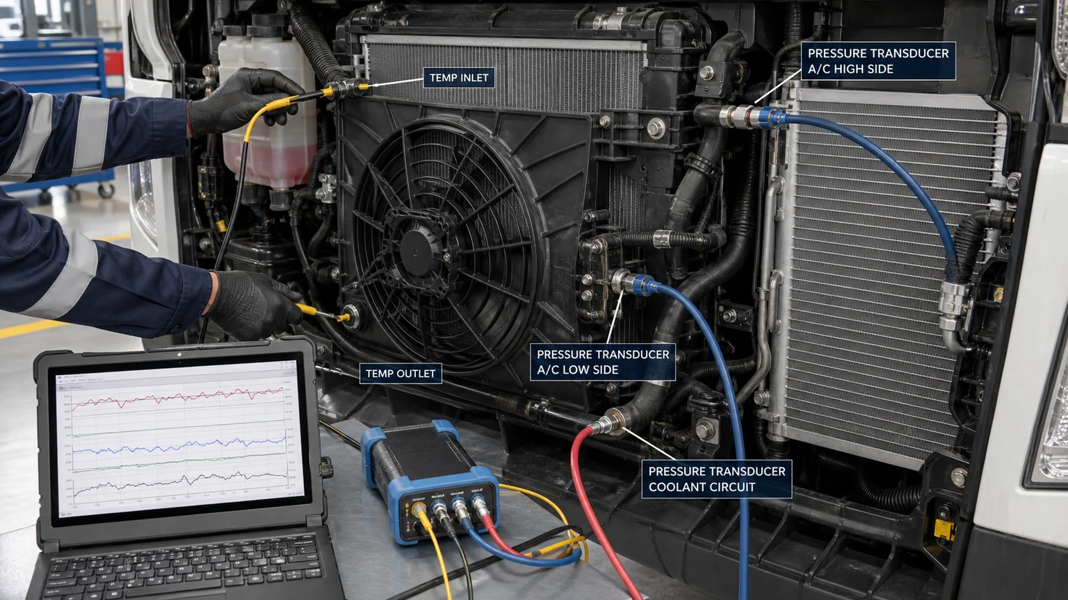
Temperature measurements change when the probe moves from a metal tube to a rubber hose, from an inlet tank to the center of a core, or from a clean surface to a reflective one. Define probe locations and attachment method. For electrical measurements, define the circuit, conductor, command and voltage reference. For pressure, define whether the value comes from a vehicle sensor, service gauge, differential sensor, or test port. Store units and tool identity with the record.
A baseline is a range, not one perfect number. Collect enough healthy events to show normal variation across ambient temperature, duty and maintenance state. Note recent coolant service, refrigerant repair, core cleaning, fan replacement, software update, or grille-shutter change. The fleet can then identify a shift that persists beyond expected variation instead of reacting to every outlier.
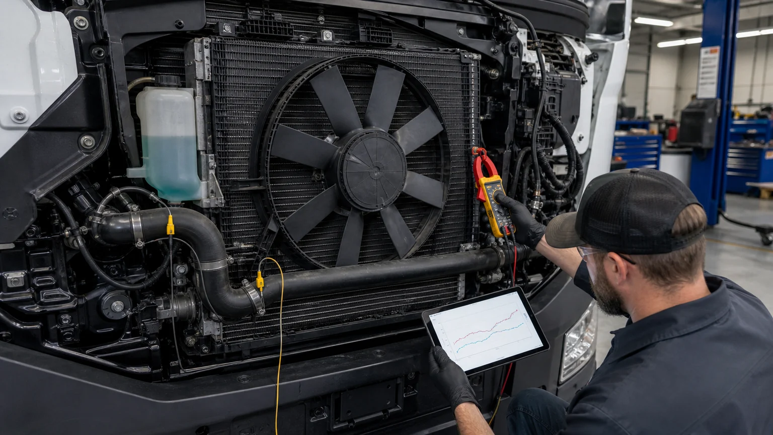
Fan current becomes meaningful when it is paired with command, voltage, speed and airflow.
An electric cooling fan converts electrical power into airflow. Current can rise because bearing friction, blade contact, debris, motor deterioration, high system voltage, or increased airflow resistance loads the motor. Current can fall because supply voltage is low, a winding or control stage is failing, the command is lower, or the motor is not producing the expected torque. Neither direction proves one cause.
For a repeatable fan check, record battery/charging-system voltage, commanded duty or speed, actual speed when available, current, rotation direction, blade condition, shroud clearance, grille shutters, duct seals, heat-exchanger blockage, and ambient condition. A clean fan drawing more current at the same command may justify inspection of bearings, blade balance, motor and control. A fan drawing normal current while airflow falls may point to blade damage, wrong rotation, recirculation, missing seals, or core restriction.
Inspect connector voltage drop under load. A corroded terminal can reduce motor voltage and generate heat without immediately setting a code. Compare supply and ground drop at a defined command. Thermal evidence at the connector, discoloration, looseness, damaged seals, or fretting adds value to the work order. Do not install a higher-current replacement motor into an undersized or damaged circuit without verifying the approved application.
High-side and low-side pressure respond to ambient temperature, cabin load, compressor command, refrigerant mass, airflow, expansion control, and system architecture. Pressure alone cannot distinguish an overcharge, airflow restriction, internal condenser restriction, expansion issue, compressor problem, or sensor error. A trend becomes more useful when the fleet also records line temperatures, vent or cabin performance, condenser fan command, compressor speed or control, and the service procedure used.
A gradual rise in high-side pressure at similar ambient and compressor demand may justify cleaning and airflow inspection before an A/C condenser is ordered. If pressure rises while fan speed or airflow declines, the fan path is the stronger first inspection. If pressure behavior changes after refrigerant service, confirm recovery, evacuation, specified charge mass, oil handling, and contamination control. An inaccurate refrigerant charge can imitate component degradation.
Electric compressors add another layer. The vehicle may vary compressor speed for cabin, battery, or heat-pump demand. Record requested and actual operation, power/current where safely available, fault codes, refrigerant/oil application, and high-voltage isolation status. A compressor should not be condemned merely because pressure differs from a belt-driven vehicle at idle.
Coolant temperature at one sensor reports a system condition, not the condition of the radiator alone. Heat input, coolant flow, thermostat or valve position, pump/engine speed, airflow, reservoir pressure, coolant mixture, and measurement location all influence the value. A useful fleet trend pairs inlet and outlet temperature with operating load and flow-related evidence.
A declining temperature drop across a heat exchanger under comparable load can accompany reduced heat transfer, but it may also result from increased flow or lower heat input. A rising drop can accompany improved heat rejection or restricted flow. Temperature difference is therefore not diagnostic without flow and heat-load context. Interpret the direction with pump command/current, fan operation, core cleanliness, thermostat/valve state, and the protected component’s temperature. The goal is to show whether heat entered the coolant, moved through the circuit, and left at the exchanger.
Coolant service history matters. Wrong concentration, mixed coolant chemistry, scale, oil contamination, sealant, or debris can change heat transfer and pressure drop. Record fill quantity, coolant specification, appearance, refractometer or concentration check where appropriate, bleed procedure, and any filter inspection. A new radiator or pump will not correct recurring contamination from another failed component.
Use when a value remains inside healthy variation but begins to move. Confirm sensor validity, operating-condition tags, and data quality. Increase sampling at the next scheduled service rather than creating an urgent parts order. An observation should name the signal and condition: for example, fan current has increased at 80% command during three comparable hot-idle tests.
Use when the trend persists, crosses a fleet-defined band, or appears with a second supporting signal. Inspect physical blockage, leaks, connectors, voltage drop, coolant condition, hose routing, fan/shroud clearance, pump operation, valve position, refrigerant service history, and sensor plausibility. Clean, repair, or retest as the evidence requires. Record what changed after the inspection.
Use when controlled testing localizes the failed part or when physical damage, leakage, electrical failure, excessive play, confirmed restriction, or unacceptable performance is documented. Build the order from OE references, dimensions, ports, voltage, connectors, control type, media, mounting and application—not from the dashboard alert. Keep the before-and-after trend so the fleet can confirm that the repair restored the baseline.
A consistent measurement map turns isolated readings into a comparable trend record.
Asset ID, VIN/application, mileage or hours, cooling package and installed part variant.
Date/time, ambient temperature, humidity where relevant, route/duty, vehicle speed and load.
Coolant type/condition, refrigerant and recent service history.
Commanded and actual fan, pump, valve and compressor states.
Supply voltage, current and voltage-drop measurements at defined commands.
Pressure values, source of pressure data, units and measurement state.
Temperature locations, values, units, tool and attachment method.
Fault codes, warnings, freeze-frame data and customer complaint.
Photos of core condition, connectors, leaks, labels, ports, mounts and packaging when a part is involved.
Inspection action, part decision, result and next sampling date.
The data sheet should be short enough for technicians to complete but specific enough to reproduce the condition. Mandatory fields can be automated from telematics, while physical evidence and measurement context are added at inspection. If a field is unknown, mark it unknown rather than copying an assumed value.
Sensor drift, changed software, replacement parts, tool differences, seasonal ambient changes, new routes, heavier loads, and altered grille or body equipment can shift the baseline. Review alerts after major configuration changes. A model that ignores maintenance actions may interpret a new fan or cleaned core as an unexplained anomaly. Keep versioned baselines and do not combine different component variants without evidence that they behave similarly.
Telematics can identify where to inspect, but it cannot see bent fins between stacked cores, a loose terminal, contaminated coolant, an incorrect fan blade, or a stressed refrigerant line. Preserve a human verification step. Conversely, a clean visual inspection does not prove normal pressure drop, airflow, or electrical load. The strongest programme combines normalized data with targeted physical tests.
Not every signal needs second-by-second storage for the life of the vehicle. A slowly changing radiator temperature baseline can be summarized at defined route or load points. An intermittent fan-control dropout may require higher-resolution capture around the event. Refrigerant pressure during a controlled A/C test needs enough resolution to show command and response, while a monthly connector inspection remains a manual record. Set the sampling rate according to how quickly the suspected failure develops and how the controller changes its command.
Retain raw data around an alarm, then store summarized features for longer-term comparison: maximum and median fan current at a defined command, time to reach a protected temperature, coolant inlet/outlet difference at a defined load, high-side pressure relative to ambient, or the percentage of charging time spent at maximum cooling request. Document every calculation. If the fleet changes the definition, version the metric so old and new records are not silently mixed.
Avoid a universal percentage rule such as “replace the fan after current rises ten percent.” Measurement error, voltage, temperature, motor design and airflow load can make that unsafe. Use fleet-derived warning bands, manufacturer limits where available, and supporting signals. A trend can trigger inspection at a conservative level; replacement requires a localized fault or failed acceptance criterion.
A group of delivery vehicles shows normal coolant temperature on the road but two vehicles trend hotter during long A/C idle. The first data review shows that both vehicles command high fan speed. One vehicle draws progressively higher fan current and has falling measured airflow; the other draws lower-than-group current and shows voltage loss at the connector. The same symptom therefore produces two different work orders.
On the high-current vehicle, inspection finds debris between the condenser and radiator plus early bearing roughness. The core stack is cleaned, airflow is retested, and the fan is replaced only after current remains excessive at the controlled command. On the low-current vehicle, the motor is initially capable, but a heated, loose terminal creates voltage drop. The connector and circuit are repaired, and the original fan returns to the healthy baseline. Replacing both fan assemblies at the first high-temperature complaint would have left one electrical fault unresolved.
The record should show ambient temperature, idle time, A/C request, coolant temperature, fan command, voltage, current, airflow test method, connector drop, core condition, repair and post-repair result. That compact case becomes training evidence for future inspections and helps purchasing distinguish motor demand from harness demand.
A fleet observes rising high-side pressure and weaker low-speed cooling on several vehicles that were serviced by the same location. Before ordering condensers, the fleet compares charge records, ambient-normalized pressures, fan operation and line temperatures. The vehicles share inconsistent recovered and charged quantities, while clean unserviced vehicles of the same configuration remain inside the baseline. The corrective action is a service-process audit, equipment calibration check, refrigerant identification and controlled recharge—not a bulk condenser replacement.
If one vehicle still shows high pressure after the service process is corrected, then inspect airflow, fin condition, internal restriction evidence and compressor/expansion control. Predictive data is most valuable here because it identifies a common event across assets. A batch of parts, a technician procedure, a route or an environmental exposure can produce a pattern that no individual repair order reveals.
Assign ownership for baseline changes, sensor validation, alert review and closure. A maintenance engineer or fleet analyst should approve new asset groups and metric definitions; technicians should record physical findings; purchasing should link part numbers and batches; and warranty staff should capture return outcomes. Close an alert with a reason such as normal condition, data error, cleaned/adjusted, wiring repaired, part replaced, or further monitoring. Unclosed alerts quickly make the system noisy and ignored.
Audit false positives and missed failures quarterly or after a meaningful event volume. If many alerts lead to no physical issue, improve operating-condition normalization or supporting-signal requirements. If failures occur without warning, check whether the relevant signal was sampled, whether the threshold was too broad, or whether the failure mechanism was not measurable with current data. Predictive maintenance improves through recorded outcomes, not through adding more dashboard graphics.
A supplier enquiry should include the asset/application, OE number, component label, ports, connectors, dimensions, mounts, media, control type, and the trend that localized the problem. For a fan, provide command, current, voltage and airflow evidence. For a condenser or compressor, provide refrigerant service and pressure/temperature context. For a radiator or pump, provide coolant condition, temperature and flow-related evidence.
The same record strengthens warranty decisions. It separates a genuine shift from an isolated complaint, shows the condition before replacement, and confirms whether the repair restored performance. Preserve returned parts and batch/lot data when a pattern appears across several assets. A cluster tied to one batch, route, installation practice, or service event is more actionable than unrelated individual returns.
The best use of current, pressure, and temperature trends is to schedule the right inspection before a vehicle loses service. Normalize the data, compare comparable assets, look for persistent multi-signal changes, verify the physical system, and then localize the failed boundary. Predictive maintenance should reduce emergency downtime and unnecessary parts replacement at the same time.
For a parts enquiry, provide the OE reference, application details, normalized current/pressure/temperature trends, label and connector photos, ports, dimensions and failure evidence. Elecdura can then scope the relevant cooling components around a verified need rather than a generic alert.