English
Views: 0 Author: Site Editor Publish Time: 2026-07-29 Origin: Site
A radiator fan motor should not be replaced just because the fan is not spinning. A correct test starts with the circuit: fuse condition, relay output, power feed, ground, fan command, connector condition, voltage drop, and current draw. Only after those checks should the motor be judged. A fan that runs on direct 12V power may still be weak under load. A fan that does not run from the vehicle harness may still be healthy if the relay, fan control module, resistor, coolant temperature signal, or A/C pressure request is missing.
The practical answer is this: confirm battery voltage and ground at the fan connector, command the fan with a scan tool or operating condition if possible, test the motor directly with fused jumper leads, measure running current with a clamp meter, and inspect the connector for heat damage. A healthy radiator fan motor should start quickly, run smoothly, pull air strongly through the radiator or condenser, and keep current draw within the expected range for that specific fan design. Slow startup, grinding noise, high current, melted terminals, repeated fuse failure, or a motor that only works when tapped usually points toward replacement.
Radiator fan testing should consider the motor, blade, shroud, connector, resistor or module, and vehicle control strategy as one working system.
The cooling fan is a high-current electrical load. On many vehicles it is also a controlled load, not a simple on/off accessory. Older systems may use a fuse, relay, two-wire motor, and a temperature switch. Other systems use low-speed and high-speed relays. Many later vehicles use a resistor, an integrated fan control module, a PWM command from the ECU, or a brushless motor with electronics built into the fan assembly. Some vehicles switch the fan on because coolant temperature is high. Others switch it on because the A/C system requests condenser airflow even when coolant temperature is normal.
This is why direct battery testing is useful but incomplete. If the fan motor spins when connected to 12V, the motor is not fully open-circuit, but that does not prove the whole assembly is healthy. It may be slow, noisy, overloaded, or unable to reach the airflow needed at idle. If the motor does not spin from the vehicle harness, that does not automatically prove the motor is bad. The relay may not be closing, the fan control module may not be receiving command, the coolant temperature sensor may not be reporting correctly, or the ground side may have too much resistance.
For repair shops, this distinction prevents wasted labor. For importers and distributors, it also matters for warranty control. A returned radiator fan motor may have been blamed for a problem caused by a burned connector, undersized wiring repair, wrong fan control module, or mismatched resistor. A stronger diagnostic process reduces false claims and helps buyers specify the correct replacement part the first time.
A basic fan motor check can be done with simple tools, but the quality of the result depends on how the test is performed. A jumper wire touched briefly to the battery may tell you if the motor is completely dead, but it will not show voltage drop, current draw, controller command, or load behavior. For a useful decision, prepare the following tools before removing the fan assembly.
Tool | What it confirms | Why it matters |
|---|---|---|
Digital multimeter | Battery voltage, ground, continuity, voltage drop, relay output | Prevents replacing a fan motor when the real fault is supply or ground |
Fused jumper leads | Whether a two-wire motor can run directly from battery power | Protects the vehicle and tester if the motor is shorted |
Clamp meter | Startup and running current draw | Shows whether the motor is overloaded, dragging, or electrically weak |
Scan tool | Fan command, coolant temperature, A/C pressure request, DTCs | Important for ECU-controlled and PWM/module-controlled fans |
Wiring diagram | Pin function, relay path, fuse size, resistor or module layout | Prevents guessing on multi-speed or multi-pin assemblies |
The fused jumper lead is important. Radiator fan motors can draw high current, especially when starting from rest. A shorted motor or incorrect polarity connection can damage wiring quickly. Use a fuse close to the battery side of the jumper, keep hands and loose clothing away from the blade, and secure the fan assembly before applying power. A loose fan assembly can jump or twist when the motor starts.
Before connecting test leads, inspect the physical assembly. Broken blades, a cracked shroud, missing balance weights, bent mounts, rubbing marks, foreign material, or a fan blade contacting the shroud can make the motor look electrically weak when the real issue is mechanical drag. A motor that draws too much current may be struggling against a warped shroud or seized bearing. A motor that works on the bench may fail after installation if the shroud is deformed and the blade touches under vibration.
Spin the blade by hand with the connector unplugged and the ignition off. It should move smoothly without scraping. Some brushless or electronically controlled motors may not freewheel like a simple brushed motor, but there should still be no grinding, wobble, or hard stop. Check whether the fan assembly has two wires, three wires, four wires, a separate resistor, a separate module, or an integrated controller. That visual check determines which test path is appropriate.
Also inspect the connector. Darkened plastic, green corrosion, loose terminals, swollen seals, or a connector that smells burned are major clues. A high-current fan can run poorly if terminal contact is weak. The motor may be blamed because the fan turns slowly, but the real cause may be a voltage drop across a damaged connector. For wholesale replacement programs, connector condition is one of the first photos that should be requested from customers before approving a warranty claim.
If the fan does not operate in the vehicle, start with the fuse and relay path. A blown fuse is not just a part to replace. It is evidence. If the replacement fuse blows again, the circuit may have a short, the motor may be drawing excessive current, the fan blade may be locked, or wiring may be damaged. Replacing only the fuse without measuring current can hide the real problem until the next overheating event.
A relay test should confirm both the control side and the load side. The coil side needs command and ground. The load side needs battery supply and a low-resistance path to the fan. On simple systems, swapping the relay with a known good relay of the same rating can be a quick screen. A better test is to verify voltage at the relay feed, output voltage when commanded, and voltage at the fan connector under load.
Do not assume a relay output is good just because voltage appears on a meter with the fan disconnected. A weak contact can show voltage with no load but fail when the fan tries to draw current. This is where voltage drop testing becomes more useful than a simple continuity check. A circuit can have continuity and still be unable to carry current well enough for a cooling fan.
With the fan commanded on, measure voltage at the fan connector. On a simple 12V two-wire motor, you normally expect battery voltage or charging-system voltage at the power side and a strong ground on the ground side. If the engine is running, charging voltage may be around 13.5V to 14.5V depending on the vehicle and charging strategy. What matters is not only the number at the connector with the fan unplugged, but the voltage available when the fan is connected and trying to run.
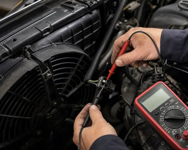
Voltage drop testing separates a weak motor from a poor connector, relay output, or ground path.
A good practical test is to back-probe the connector with the fan connected, command the fan on, and measure voltage across the motor terminals. If voltage is low, move upstream. Measure from battery positive to fan positive while the fan is commanded on. Then measure from fan ground to battery negative. A large voltage reading on either path indicates voltage drop. High voltage drop on the positive side points toward fuse, relay, wiring, or connector resistance. High voltage drop on the ground side points toward ground cable, ground point corrosion, or connector terminal weakness.
Voltage drop matters because fan motors are power-hungry. A small resistance that would not affect a sensor circuit can seriously reduce fan speed. Lower fan speed means less airflow through the radiator and condenser, which often shows up as overheating at idle, A/C warm at idle, or fan cycling that sounds abnormal.
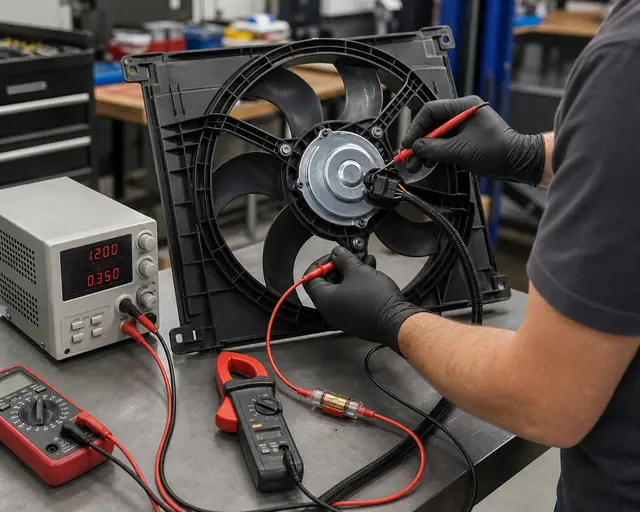
The direct 12V test is useful when the motor is a simple two-wire brushed motor or when the service information confirms that direct power is allowed. Disconnect the fan connector. Use fused jumper leads. Connect positive to the fan power terminal and negative to the fan ground terminal. The fan should start immediately and run at full speed without rough noise, hesitation, smoke, or connector heating.
A fused 12V bench test is useful only after the circuit, connector, and current draw are checked together.
If the motor does not run, reverse only if the wiring diagram confirms polarity is not fixed or if the motor is designed as reversible. Most radiator fan motors are polarity-sensitive in practical application because blade direction and airflow direction matter. A fan that spins backward may move much less air even if the motor appears strong. For a complete fan assembly, airflow direction must be checked through the radiator or condenser side, not judged only by blade movement.
If the fan starts only after tapping the motor, the brushes, commutator, or internal connection may be worn. If it starts slowly, squeals, or draws very high current, replacement is usually safer than reusing it. If it runs strongly on direct power but not in the vehicle, return to the control circuit: relay, resistor, module, temperature input, A/C pressure input, ECU command, or wiring.
Do not direct-power every modern fan assembly. Some fans with integrated electronics, PWM control, or brushless motors require a specific command signal. Applying battery voltage to the wrong pins can damage the controller. Multi-pin fans need wiring information before testing. If there are three or more terminals, identify power, ground, signal, feedback, and module pins first.
A fan that spins is not automatically a good fan. Current draw shows whether the motor is working efficiently under load. Use a DC clamp meter around the fan power wire. Measure the initial inrush current and the running current after the fan stabilizes. Compare the reading with the vehicle service specification when available. If no exact specification is available, use general ranges only as a warning guide, not as a final pass/fail rule.
Many passenger-vehicle radiator fan motors may run in the rough range of 7A to 20A depending on motor size, blade diameter, speed, and whether it is single or dual fan. Larger dual-fan or heavy-duty assemblies can draw more. Startup current can be much higher than steady running current. The correct value depends on the fan design, voltage, temperature, bearing condition, blade load, and control mode.
Test result | Likely meaning | Recommended decision |
|---|---|---|
No current, no movement | Open motor, no supply, no ground, or wrong test pins | Confirm power/ground, then replace if direct test fails |
Very high current, slow movement | Dragging bearing, locked blade, internal short, shroud contact | Inspect mechanical drag; replace motor or assembly if confirmed |
Normal current, weak airflow | Wrong blade direction, damaged blade, wrong assembly, blocked radiator | Check airflow direction, blade, shroud, and part matching |
Low current, slow speed | Voltage drop, weak module output, wrong low-speed command, worn motor | Check voltage under load and control signal before replacing |
Current rises as motor runs | Heat-related bearing drag or internal winding issue | Run longer test; replace if current climbs beyond specification |
Current testing is especially valuable for distributors handling warranty claims. If a fan assembly is returned as "not cooling enough", a direct spin test may pass. A current draw test, noise test, and airflow check can reveal whether the motor is weak, the blade is wrong, or the customer installed the correct motor into a damaged shroud. For replacement sourcing, current rating and fuse compatibility should be part of the confirmation process.
Many vehicles do not run the fan at one fixed speed. A two-speed relay system may use one relay path for low speed and another for high speed. A resistor system may reduce voltage for low-speed operation. A control module may regulate duty cycle or motor speed based on ECU command. A brushless fan may have integrated electronics and feedback logic. Testing these systems as if they were simple two-wire motors can produce wrong conclusions.
If low speed does not work but high speed does, inspect the resistor path, low-speed relay, connector heat, and wiring. If high speed does not work but low speed does, check the high-speed relay, high-current fuse, and control command. If the fan runs constantly, check whether the system is in fail-safe mode because a sensor input is missing. If the fan never runs, check whether the ECU is actually requesting fan operation.
A separate fan control module can fail in different ways. It may stop sending power to the fan, keep the fan running after shutdown, run only one speed, or overheat internally. The module should not be replaced until its power, ground, command, and output have been checked. For buyers comparing control parts, Elecdura's fan control module vs cooling fan resistor guide is useful because the two parts solve different control problems and cannot be matched by appearance alone.
Some applications use a dedicated cooling fan resistor, such as OE-style resistor parts for specific Ford, Fiat, Chevrolet, or similar platforms. In those systems, a failed resistor may create a missing low-speed fan, unstable fan switching, or overheating in traffic. A product such as the F5RZ8L603AC engine cooling fan resistor illustrates why OE number, connector layout, and application range matter during sourcing.
Whenever possible, command the fan through the vehicle before removing the assembly. A scan tool may allow active fan control. If active control is not available, observe fan behavior as coolant temperature rises, when the A/C is turned on, or when service information says the fan should run. Watch live data for coolant temperature, A/C pressure, fan command percentage, and related trouble codes.
If the ECU commands 80 percent fan speed but the fan does not respond, check module output, power, ground, and motor current. If the ECU never commands the fan even when temperature is high, the problem may be sensor input, ECU logic, wiring, or a scan data misunderstanding. If the A/C is on but the fan does not run, check whether the vehicle strategy requires fan operation under that condition and whether A/C pressure data is valid.
This step is important because many cooling complaints occur at idle. A fan may not be commanded during a cold test in the workshop, so the technician assumes it is dead. Conversely, a fan may run during a direct test but fail to receive the correct command in traffic. Testing the system under the condition that creates the complaint is more reliable than testing only the removed motor.
Some vehicles allow replacement of the motor alone. Others are better serviced as a complete fan assembly with blade, shroud, resistor, module, and mounting structure. The right decision depends on design, labor cost, parts availability, and failure mode. If the shroud is cracked, the blade is damaged, the bearing has caused blade contact, or the controller is integrated, a complete assembly is usually safer. If the motor is separately serviceable and the shroud/blade are good, motor-only replacement may be economical.
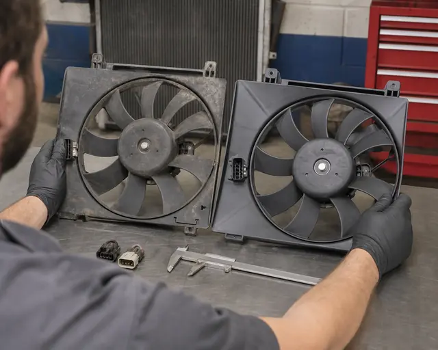
For replacement orders, connector, shroud depth, mounting points, blade direction, and motor output should be checked together.
For wholesale customers, the replacement decision also affects inventory planning. A distributor may stock fast-moving complete radiator cooling fan assemblies for high-demand applications while carrying selected motor-only items for platforms where serviceability is common. The wrong stocking decision creates slow inventory, excessive returns, and fitment disputes. The correct decision starts with OE references, application range, photos, connector layout, control type, and quality testing requirements.
Situation | Motor-only replacement may work | Complete assembly is safer |
|---|---|---|
Simple two-wire brushed motor | Yes, if blade and shroud are undamaged | Yes, if labor savings or warranty control matter |
Integrated control module | Only if motor is sold separately and tested with correct electronics | Often preferred because electronics and motor age together |
Broken blade or cracked shroud | No, unless separate parts are replaced together | Yes, airflow and balance depend on the full assembly |
Melted connector | Only after harness and terminal repair | Often preferred if motor current is also high |
High current draw | Possible if motor alone caused the draw | Preferred if mechanical drag or assembly distortion is involved |
The first mistake is testing the fan with weak jumper wires. Thin wire, loose clips, or long temporary leads can create voltage drop. The fan may turn slowly, making the motor look weak. Use suitable wire size, a fuse, and firm terminal contact. If possible, measure voltage at the motor while the direct test is running.
The second mistake is ignoring ground quality. A fan motor can receive battery voltage on the power side and still run poorly because ground resistance is high. Always test both sides of the circuit. A dirty ground point, repaired harness, or corroded terminal can create intermittent overheating complaints.
The third mistake is judging airflow by sound. A loud fan is not always a strong fan. Blade design, shroud seal, rotation direction, and motor speed determine airflow. A fan spinning backward after incorrect wiring may sound active but move insufficient air through the radiator. On dual-fan assemblies, one weak fan can be hidden by the sound of the other.
The fourth mistake is replacing a control module without testing the motor. A motor with excessive current draw can damage a new module. If a module has failed from heat or overload, measure motor current before installing the replacement. This is a common reason for repeat failures in high-current fan circuits.
The fifth mistake is matching by appearance alone. Two fan assemblies can look similar but differ in blade pitch, motor power, connector pin count, shroud depth, mounting tabs, resistor value, or PWM control logic. For B2B sourcing, appearance should support confirmation, not replace OE-number and application matching.
Importers, wholesalers, and repair supply chains should treat radiator fan motor testing as a sourcing specification, not only a workshop activity. A buyer who understands the test can ask better questions before placing a bulk order. This reduces mismatched inventory and prevents returns that are caused by incomplete application data.
OE number and any supersession numbers.
Vehicle make, model, year, engine, and market region.
Motor voltage: 12V, 24V, or special system requirement.
Connector shape, terminal count, locking tab, and wiring position.
Fan blade diameter, blade count, rotation direction, and shroud depth.
Single fan or dual fan assembly.
Simple relay, resistor, external module, integrated module, or PWM control.
Expected current draw or factory test current when available.
Noise, vibration, heat, and endurance test requirements.
Packaging requirement for long-distance shipment and warehouse handling.
Elecdura focuses on B2B cooling parts supply, so these fields are part of the conversation when customers request radiator fan motors or complete cooling fan assemblies. If the buyer can provide OE numbers, photos of the original fan, connector close-ups, and target quantity, the replacement path becomes much clearer. If the buyer only provides a vehicle name, the risk of wrong connector, wrong fan speed, or wrong control strategy increases.
A repair shop normally tests one vehicle. A distributor needs to think about repeatability across many units. For that reason, bench testing should be standardized. A useful incoming or sample inspection process includes visual inspection, connector verification, motor startup test, running current test, noise check, vibration check, and airflow direction confirmation. For controlled fans, the test fixture must simulate the correct power and signal conditions.
Do not compare two different fan models only by current draw. A larger blade, stronger motor, or heavy-duty assembly may draw more current by design. Compare the tested unit against the correct sample, OE specification, or agreed supplier data. A low current number is not automatically better if airflow is weak. A high current number is not automatically bad if the model is designed for high-load operation and protected by the correct fuse and wiring.
For private-label programs, ask the supplier how each batch is checked. Useful documents include sample test videos, current draw records, connector photos, dimensional checks, packaging photos, and application cross-reference files. These records make it easier to answer customer questions later, especially when a market has several similar fan assemblies for the same model family.
Confirm the complaint: overheating at idle, A/C warm at idle, fan not running, fan running constantly, noisy fan, or repeated fuse failure.
Inspect the fan, blade, shroud, connector, wiring, and signs of overheating.
Check fuse condition and relay operation. If the fuse blows again, stop and look for short or overload.
Command the fan with a scan tool or create the correct operating condition according to service information.
Measure voltage and ground at the fan connector under load.
Measure voltage drop on the positive and ground paths.
Use a fused direct 12V test only when the fan design allows it.
Measure current draw and compare with the correct specification or known-good sample.
Check whether the system uses a resistor, relay set, module, PWM signal, or integrated controller.
Decide whether the motor alone, control part, harness repair, or complete fan assembly is the correct replacement.
Replace the radiator fan motor or assembly when the motor fails a fused direct-power test, starts only intermittently, runs with grinding noise, draws excessive current, overheats its connector, or cannot provide the required airflow after power and ground are confirmed. Do not replace it yet when there is no fan command, no relay output, weak ground, missing module signal, damaged connector, or an unverified sensor input. In those cases, the motor may be innocent.
The best test is not one single measurement. It is a chain of evidence: command, voltage, ground, direct operation, current draw, airflow, noise, connector condition, and control strategy. That chain gives repair shops a defensible replacement decision and gives wholesale buyers a better way to specify the correct product. When the test points toward replacement, Elecdura can help match radiator fan motors and complete fan assemblies by OE number, vehicle application, connector, voltage, shroud design, and order volume.