English
Views: 0 Author: Site Editor Publish Time: 2026-08-25 Origin: Site
EV fast-charging power can fall because the vehicle is protecting the battery, but “thermal derating” is not a diagnosis and it does not identify a replacement part. A complete parts decision must show where the heat path stopped working: inside the battery coolant circuit, across the refrigerant chiller, at the electric compressor, through the condenser or radiator, in the fan and ducting, or in the valves, sensors, and controls that coordinate them.
Start with charging-session evidence, not a parts list. Record battery temperature before charging, ambient temperature, starting state of charge, charger power, requested versus delivered charging power, coolant inlet and outlet temperatures, compressor and pump commands, fan operation, diagnostic codes, and the time when power begins to reduce. The same vehicle can charge at different rates because of battery state, charger capability, software limits, cell balancing, or temperature. A thermal component should be ordered only after the data points to its boundary.
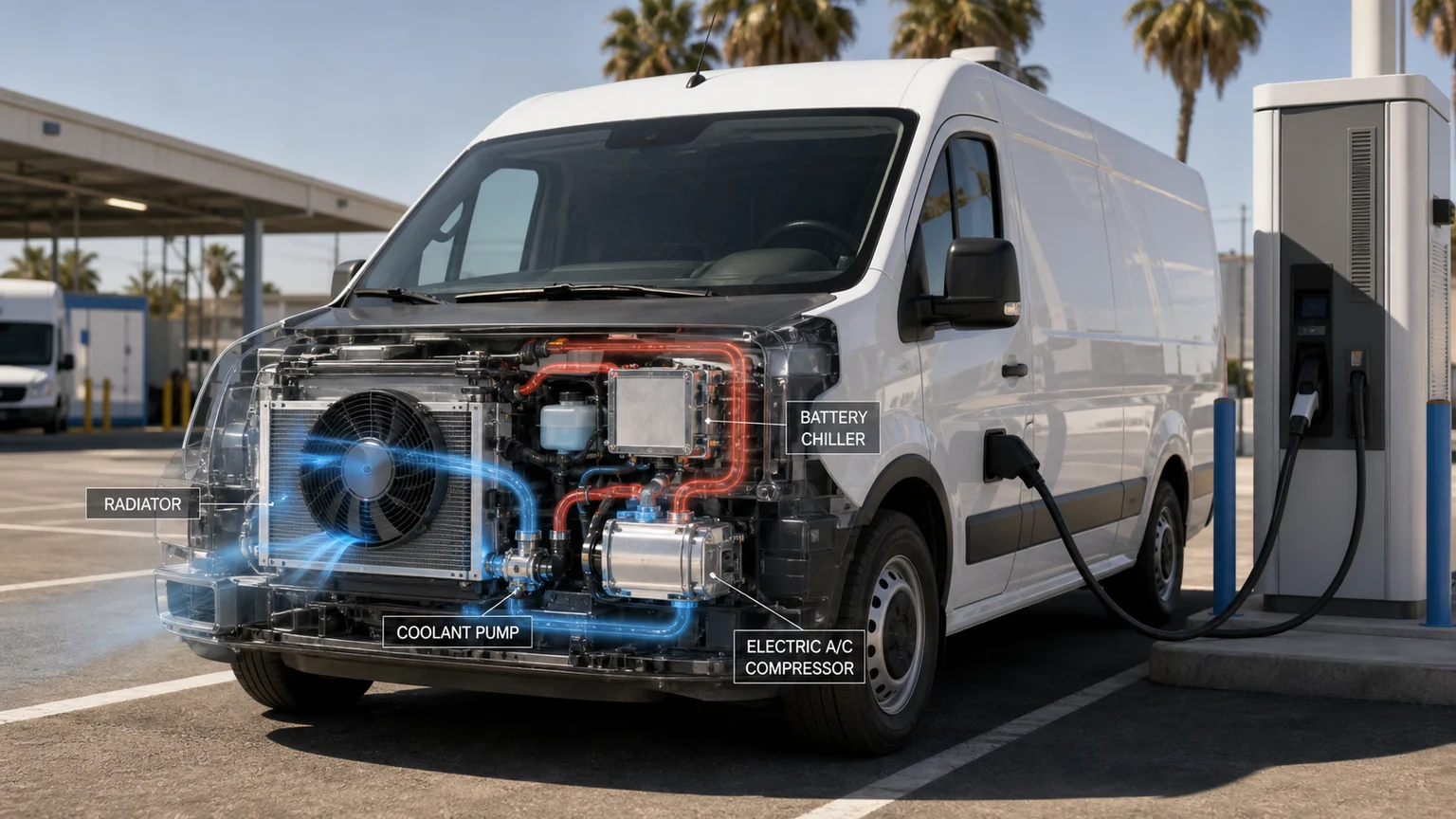
Fast charging depends on the coordinated performance of the coolant, refrigerant and air-side subsystems.
During fast charging, electrical losses create heat in the battery cells, busbars, connectors, and power electronics. In one common liquid-cooled architecture, the vehicle moves battery heat into a coolant plate, circulates it with an electric pump, and then rejects it through a radiator, a refrigerant-to-coolant chiller, or both. If active chilling is requested, the electric A/C compressor and refrigerant circuit move that heat to a condenser or another heat-rejection device. Other EVs package and route these functions differently, so this heat path is an example rather than a universal schematic. The front fan and ducting must then move enough ambient air through the heat exchangers while the vehicle is stationary.
Derating occurs when the battery-management system or thermal controller determines that a protected temperature, temperature spread, pressure, current, or other operating limit is being approached. The charging-power reduction may be normal for the condition. It becomes a repair concern when the vehicle performs materially worse than its validated baseline under comparable state of charge, ambient temperature, battery preconditioning, and charger conditions, or when faults and measured thermal behavior show that commanded cooling is not being delivered.
Evidence | Why it matters | Common mistake |
|---|---|---|
Starting state of charge | Charging power normally changes across the battery’s charge curve. | Comparing a low-state-of-charge session with a session that started near the upper range. |
Battery start temperature | A cold or already-hot pack can follow a different protected strategy. | Calling any lower power a chiller fault. |
Ambient and solar load | Front-end heat rejection and cabin demand change with weather. | Ignoring a hot-soaked vehicle or direct sun. |
Charger capability and sharing | The external charger may limit power independently of the vehicle. | Replacing vehicle parts for an infrastructure limit. |
Requested versus delivered power | Shows whether the vehicle or charger is limiting the session. | Using only the peak number displayed to the driver. |
Temperature and command trends | Shows whether cooling demand rose and whether the system responded. | Judging the system from one scan-tool snapshot. |
A repeatable test does not need to abuse the battery. Use approved procedures and safe operating conditions. Compare sessions with similar starting state of charge, battery preconditioning status, charger type, and ambient condition. If the vehicle has a known service test for pumps, valves, fans, or compressor operation, use it before disturbing refrigerant or coolant connections. Preserve the scan record and timestamps so the temperature response can be aligned with charging power.
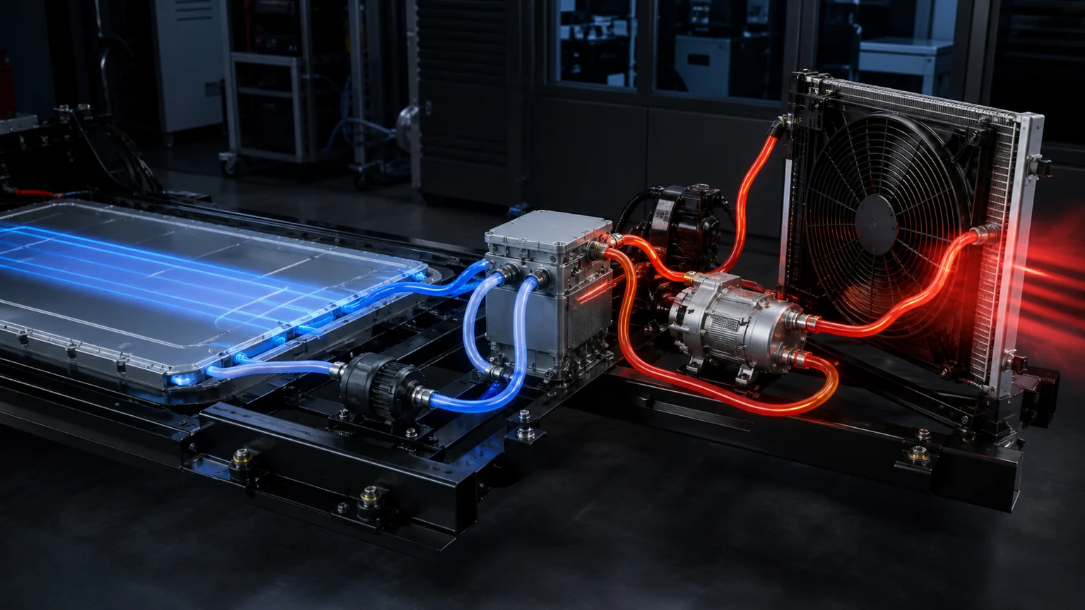
Following the heat path localizes restrictions before an expensive component is condemned.
The battery cold plate transfers cell or module heat into coolant. The pump then moves the coolant through hoses, manifolds, valves, a radiator, and/or the chiller. If coolant is low, aerated, contaminated, incorrectly mixed, or restricted, temperature can rise even when the chiller and compressor are capable. A weak pump, wrong rotation or control, blocked filter, stuck valve, kinked hose, trapped air, or incorrect bleeding procedure can create a similar result.
Compare battery coolant inlet and outlet temperatures with pump command and operating state. A small temperature difference does not automatically prove poor heat transfer; it can also reflect high flow or a low instantaneous heat load. A large difference may occur with effective heat pickup or inadequate flow, but temperature difference alone cannot distinguish them without flow and load context. Interpret the values with charging power and coolant flow evidence. If pump speed is reported, confirm that the requested and actual values agree. Where electrical testing is permitted, current trend can add supporting evidence: unusually low or high current may reflect the load, pump design, control strategy, restriction or mechanical condition, so it is not a standalone pump-health test. Application-specific limits must come from approved information.
The chiller must transfer heat from battery coolant into the refrigerant circuit. Its performance depends on coolant flow, refrigerant mass flow, expansion control, compressor capacity, and the temperature/pressure condition entering both sides. If the coolant inlet remains hot and the outlet does not cool after active chilling is commanded, the chiller is one candidate—but so are a closed valve, low refrigerant charge, restricted expansion device, weak compressor, sensor error, and inadequate condenser heat rejection.
Use temperature probes or scan data to observe coolant change across the chiller and refrigerant behavior according to the vehicle’s service procedure. Confirm that the active-cooling mode is actually requested. A controller may intentionally prioritize cabin cooling, battery conditioning, or another thermal load. Do not condemn the chiller from an infrared image alone; reflective surfaces, insulation, flow rate, and sensor placement can mislead. If an internal cross-leak is suspected, isolate the circuits safely and preserve fluid/refrigerant evidence rather than opening the part prematurely.
An EV compressor may operate for battery cooling even when the cabin A/C is not the customer’s complaint. Match commanded speed or capacity with pressure and temperature response. A compressor that runs audibly is not necessarily producing the required refrigerant flow, while a compressor that does not run may be inhibited by an isolation fault, interlock condition, sensor input, low charge, control communication, or protected operating state.
Before quoting a compressor, document the OE number, voltage class, refrigerant, oil requirement, high-voltage and control connectors, ports, mounts, and fault evidence. If the previous compressor failed mechanically, inspect the circuit for debris and decide which components cannot be reliably flushed. A new compressor installed into a contaminated circuit can fail quickly and produce a weak warranty claim.
When the vehicle is stationary at a charger, ram air is absent. The fan system and sealed duct path must pull or push air through the A/C condenser, radiator, and any additional front heat exchangers. Dirt, leaves, plastic bags, dust, bent fins, stacked-core debris, closed shutters, missing seals, incorrect fan direction, low fan speed, or a damaged shroud can raise both refrigerant pressure and coolant temperature.
Inspect the front and the spaces between stacked cores. A clean visible front face does not prove that the rear surface or gap is clear. Confirm fan command, actual speed if available, current, rotation direction, blade and shroud clearance, and airflow across the core. A replacement condenser or radiator with incorrect fin density, depth, mounting, or duct fit can also reduce performance despite matching the main dimensions.
Observed trend | Possible boundary | Next check |
|---|---|---|
Battery coolant temperature rises while pump command stays high and chiller outlet does not cool | Coolant flow, valve position, chiller, refrigerant capacity | Verify actual pump operation, valve state, coolant flow and refrigerant response. |
Compressor command rises and high-side pressure/temperature climbs while stationary | Screening clue for condenser airflow or heat rejection; not a conclusion | Inspect fan speed, direction, shutters, duct seals, core blockage and ambient condition, then compare refrigerant charge, compressor strategy, expansion control and architecture-specific data. |
Pump current rises while flow or temperature response weakens | Restriction, air, pump wear or wrong coolant condition | Check bleed, hoses, filters, valves, coolant and pump condition. |
Charging power drops with normal battery temperatures and no cooling demand increase | Possibly non-thermal limit | Check charger capability, charge curve, state of charge, cell balance and other vehicle limits. |
Cabin cooling and battery cooling both degrade at high ambient | Shared compressor, refrigerant charge, condenser or fan capacity | Read shared refrigerant and airflow evidence before replacing either branch component. |
These patterns narrow the investigation but do not replace application data. A vehicle can use a secondary coolant loop, refrigerant branch, integrated thermal module, reversible heat pump, or dedicated radiator. Label any diagram as typical unless the application is known, and do not apply one pressure or temperature target to every EV.
Match more than hose diameter. Record the OE number, pump voltage, connector and pin count, communication or PWM control, nominal flow/pressure requirement where available, inlet/outlet orientation, mounting position, wet-running requirements, coolant compatibility, integrated electronics, and bracket or isolation features. Similar pump bodies may use different software addresses or control protocols. A pump that spins on a bench supply may still be incompatible with the vehicle controller.
For a warranty request, include pump command versus actual speed, current trend, coolant condition, evidence of dry running or air, connector condition, supply voltage, ground, and installation orientation. If debris or degraded coolant is present, identify the source before fitting another pump. Store new pumps with ports capped and protect plastic connectors from side loads.
Capture every refrigerant and coolant port, expansion valve, sensor, connector, bracket, and label. Confirm refrigerant, oil context, coolant type, pressure boundary, flow orientation, and whether the quotation includes attached valves or electronics. An integrated module may look like a single replacement unit while containing several controlled paths; a supplier needs the exact OE reference and connector/port evidence to confirm the assembly.
If the claim is low cooling capacity, provide the temperature and pressure trend that localizes the chiller. If the claim is leakage, mark the verified leak point and distinguish external impact, seal leakage, port damage, and suspected internal cross-leak. Keep refrigerant ports sealed and dry during storage and return handling.
Define whether the request covers only a condenser or radiator, or a module including fan, shroud, shutters, seals, brackets, sensors, and multiple heat exchangers. Measure core and overall dimensions, port positions, mount spacing, stack depth, fan diameter and depth, connector locations, and vehicle-side clearances. Photographs from the front, rear, sides, ports, mounts, and installed context are more useful than one catalogue image.
These physical checks establish fit and interface compatibility; they do not prove equivalent thermal performance. Use the acceptance-testing evidence below to compare heat rejection, airflow, pressure drop and control response at the required operating point.
Ask the supplier how fin protection, port caps, corner blocks, and internal restraint are handled in packaging. Front modules combine fragile fins with heavy motors and brackets; if the carton does not isolate those masses, vibration can damage the core before installation. Receiving inspection should record carton condition, labels, caps, fins, manifolds, mounts, blade clearance, and connector locks.
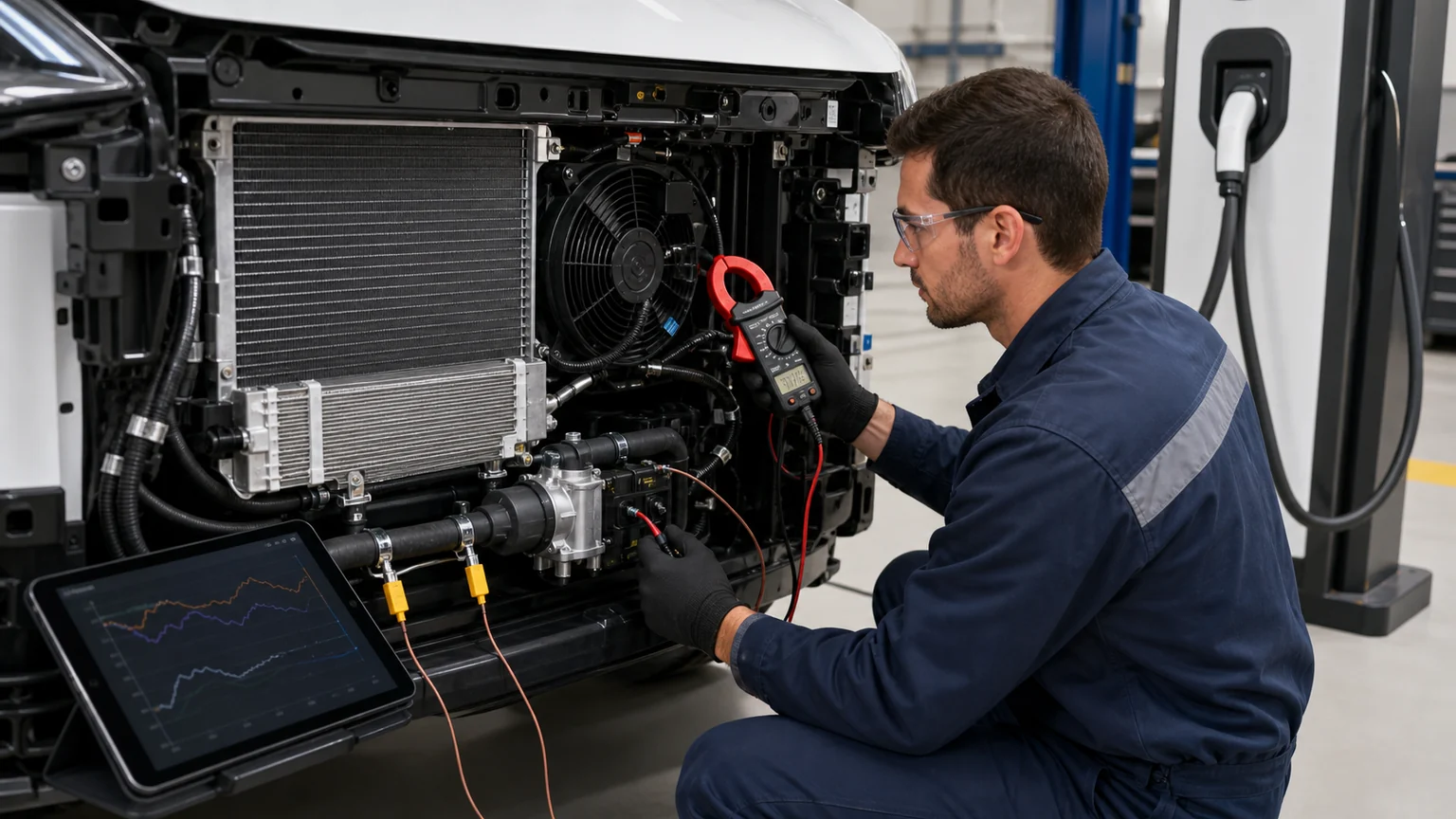
Correlated measurements distinguish a control limit from inadequate heat rejection.
Freeze the application. Record vehicle variant, software/calibration relevance, OE numbers, voltage and thermal architecture.
Inspect the sample. Compare ports, connectors, mounts, labels, dimensions, seals and packaging against an approved reference.
Check electrical interfaces. Verify connector keying, terminal arrangement, insulation and control compatibility using safe approved methods.
Check pressure and leak integrity. Use the correct medium and limits for refrigerant or coolant components; never apply a generic pressure to every heat exchanger.
Validate in the system. Run controlled charging or thermal service tests and log coolant temperatures, commands, fan operation, refrigerant response and charging power.
Retain the evidence. Store the accepted sample record, batch/lot, test data, images, packaging specification and deviation approvals.
A bulk approval should be tied to a defined duty, not to one short idle test. Include hot-soak or high-ambient conditions when they reflect the target market, but operate within the vehicle and component limits. The goal is to prove that the supplied parts restore the expected thermal response under a repeatable load—not to force the vehicle to maintain an unrealistic charging peak.
A strong claim aligns the charger record, vehicle data, and physical evidence. Note the starting state of charge, battery and ambient temperatures, charger identity and rated capability, preconditioning status, requested/delivered power, the timestamp of derating, battery coolant inlet/outlet temperatures, compressor/pump/fan commands, diagnostic codes, and any warnings. Add before-and-after data if a part was replaced.
Photograph the removed part label, connectors, ports, installation, coolant or refrigerant evidence, front-stack condition, and packaging of the replacement. Preserve recovered material and the removed component when an internal failure is alleged. This record allows the distributor to separate a genuine part defect from a charge-curve expectation, infrastructure limit, air lock, contamination issue, or installation error.
The same model line can use different battery capacities, heat-pump options, cooling packages, connectors, software strategies, or market calibrations. A model-year description may narrow the search but it does not replace the VIN/application record and OE number. Request the original label and installed photos, particularly when the part is an integrated thermal module, electric compressor, electronically controlled pump, or multi-speed fan assembly.
Heat-exchanger capacity depends on airflow, fluid flow, pressure drop, fin/tube construction, duct sealing, and the rest of the system. A thicker or denser core can increase restriction or interfere with the stack. It may also change fan load and low-speed airflow. Approve a condenser or radiator against the vehicle package and target duty rather than a single external dimension. If a supplier proposes an alternative construction, request thermal and pressure-drop evidence plus fitment validation.
An electric coolant pump can be damaged by dry running, debris, incompatible coolant, trapped air, or a restriction. If the old unit shows abnormal wear or high current, inspect the circuit before installing another. Follow the correct fill and bleed procedure, confirm valve positions, and verify that the pump is installed in the required orientation. A replacement pump should restore measured flow and temperature response, not merely clear a fault code for one short test.
A fan may rotate at the wrong direction, speed, or duty. It may have a damaged blade, excessive blade-to-shroud clearance, weak motor, incorrect control module, voltage drop, or missing duct seal. During stationary charging, those differences matter. Record commanded and actual speed when available, current draw, airflow direction, connector and control details, blade/shroud fit, and the condition of shutters and seals. A correct fan assembly must deliver the required airflow through the heat-exchanger stack without abnormal current, vibration, or recirculation.
These shortcuts have a shared cause: selecting a component before localizing the failed thermal boundary. The remedy is a controlled evidence package that follows heat, flow, power, and control signals through the vehicle. That evidence makes the RFQ more precise, the installation safer, and a later warranty decision faster.
Thermal derating is a protective outcome, not a part number. The useful sequence is to reproduce the complaint under comparable conditions, identify the active cooling mode, follow heat from the battery into coolant and refrigerant, confirm front-end heat rejection, and localize the missing temperature, pressure, flow, current, or command response.
For an aftermarket enquiry, provide the charging-session timeline, fault codes, temperature and command trends, OE references, vehicle/market application, and full photos of labels, ports, connectors, mounts, and installed context. Elecdura can review that package for chiller, electric compressor, condenser, radiator, pump, fan, and related cooling-component sourcing while keeping normal charge-curve behavior separate from evidence of a failed part.