You are here:Home » Blog » Technical Guides » Fan Clutch Fitment by Pilot, Bolt Circle, Offset, Rotation, and Blade Clearance
Fan Clutch Fitment by Pilot, Bolt Circle, Offset, Rotation, and Blade Clearance
Views: 0 Author: Elecdura Publish Time: 2026-09-01 Origin: Site
A fan clutch should be rejected before installation if its pilot or drive thread, flange pattern, fan pattern, installed height, rotation, control type, or blade clearance does not match the application. Overall diameter alone is not a reliable matching method. A disciplined comparison uses the OE number first, then photographs and measured interfaces to confirm that the clutch will center correctly, drive in the intended direction, place the fan in the shroud, and avoid the radiator under static and dynamic movement.
This measurement-led method is useful when an old label is unreadable, a vehicle has been repowered, or a catalog cross-reference needs verification. It also helps distributors prepare a precise request for a wholesale fan clutch. Measurements are supporting evidence, not permission to replace an OE application check. Two clutches can share several dimensions while using different rotation, engagement calibration or electronic control.
Safety: perform measurements with the engine off, the ignition secured, and the fan unable to start. Electrically controlled cooling systems can activate unexpectedly. Do not work near a rotating fan, and do not run an engine with a damaged, loosely mounted or interference-prone blade.
Build a fitment record before removing the old clutch
Begin with the vehicle identity: VIN or chassis number, make, model, production date, market, engine code and installed engine arrangement. Record the OE fan-clutch number, casting marks and any supplier number. Photograph the engine bay from the front and both sides, capturing fan depth in the shroud, radiator spacing, blade orientation, wiring route and hose clearance.
Mark which side of every measurement faces the radiator and which faces the engine. This sounds elementary, but reversed photographs and ambiguous “front” terminology are a common source of selection errors. Some catalogs view rotation from the front of the vehicle; others describe it from the drive side. Always write the viewing position next to clockwise or counterclockwise.
Inspect for prior modifications. Non-original water pumps, spacers, fan blades, shrouds, radiators and engine mounts change the installed stack. A part that matches the chassis catalog may not match an altered vehicle. Record spacers and adapters separately rather than including them silently in clutch height.
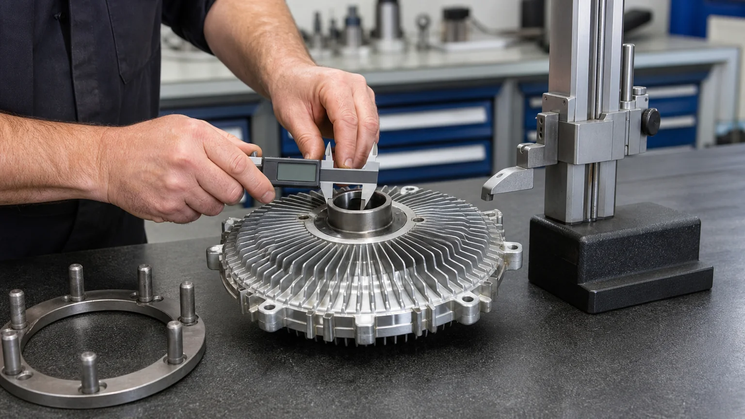
Measure the centering feature, drive or flange pattern, fan pattern and installed height with the surfaces and viewing direction clearly identified.
The dimensions that decide mechanical fitment
1. Drive interface: threaded hub or bolted water-pump flange
Many fan clutches screw onto a male or female water-pump thread. Record whether the clutch contains an internal thread or an external stud, the major diameter, pitch and effective thread length. Identify whether the thread is right-hand or left-hand from reliable application data. Trying a likely thread until it “starts” can cross-thread the pump or clutch.
Other designs bolt to a water-pump flange. Record the number of holes or studs, bolt-circle diameter, hole diameter, center pilot diameter and whether the holes are equally spaced. Four holes do not guarantee one universal square pattern. Some are slotted or use an asymmetric feature that establishes orientation.
The pilot is especially important. Bolts clamp parts together; a machined pilot often establishes concentricity. Hayden installation guidance warns against an incorrect pilot condition because off-center mounting can create vibration and damage. If the replacement bore is larger, use only an application-approved pilot bushing supplied for that combination. A loose improvised sleeve is not a precision centering solution.
2. Fan mounting pattern
The clutch-to-fan face may use studs or threaded holes. Record quantity, bolt-circle diameter, thread diameter and pitch, register or pilot diameter, and face shape. Measure the fan separately. A blade that can be forced over studs may still be incorrectly centered or may sit against the wrong surface.
Confirm which face of the blade seats against the clutch and whether a spacer or reinforcement plate is used. Reversing a fan can change airflow and move the blades out of their intended plane. Preserve all approved washers and reinforcement parts, noting their order. Replace cracked, elongated or corroded hardware rather than using tightening force to hide damage.
3. Overall height, working height and offset
“Height” is ambiguous unless the endpoints are named. Useful values include the water-pump mounting surface to the fan mounting surface, the water-pump surface to the frontmost clutch feature, and the fan mounting surface to the blade plane. Measure with a depth gauge or straightedges on clean, undamaged surfaces.
Offset describes where the fan plane sits relative to the drive surface or clutch centerline. Two clutches of equal overall height can use different fan-face positions because the housing, thermal spring or electronic control projects differently. What matters is the assembled location of the blade inside the shroud and its clearance to the radiator and engine components.
4. Body and cover diameter
Measure the maximum clutch-body diameter and identify protrusions such as a bi-metal spring, reservoir, connector or wiring bracket. Body diameter affects clearance and thermal response, but should not be used alone to estimate capacity. A larger housing can still have the wrong valve calibration or rotation.
5. Fan diameter, pitch and blade count
Measure fan diameter across opposite blade tips, checking several positions for damage. Record blade count, material, pitch direction and any part number. Do not replace only the clutch while ignoring a blade with cracks, bent tips, damaged rivets or distorted mounting holes. At engine speed, a compromised blade creates a severe hazard.
How to measure a bolt circle without guessing
For an even number of holes, the bolt-circle diameter can often be measured center-to-center across two opposite holes. When calipers cannot reach the centers directly, measure from the outside edge of one hole to the inside edge of the opposite hole for equal-diameter holes; this approximates center distance. Record the hole diameter separately.
For adjacent holes or an odd number of holes, use a verified geometric method, a bolt-circle template, or a drawing. Do not label the straight-line distance between adjacent holes as the bolt-circle diameter. Photograph the caliper position so another person can reproduce the result.
Measurements taken through corrosion, paint buildup, burrs or distorted holes can be misleading. Clean only enough to expose the original surface without removing material. A difference that appears small on a ruler may be decisive for a precision pilot or fine thread, so use suitable calipers and pitch gauges.
Thread direction, drive rotation and centering are separate checks. A clutch must seat fully on the intended surface without cross-threading or an unapproved gap.
Rotation has three different meanings
Drive rotation
Drive rotation is the direction the water-pump or drive hub turns in operation, stated from a defined viewing position. Serpentine systems may use the smooth back of a belt to drive a reverse-rotation water pump. Never infer rotation from the apparent location of the pulley alone.
Thread tightening direction
A threaded fan clutch may use a thread intended to remain tight under operating rotation. Left-hand and right-hand thread direction must be confirmed independently. The word “reverse” in a catalog may refer to pump rotation, fan airflow or thread, depending on context.
Clutch calibration and fan airflow
Internal fluid passages and valves can be designed for a particular rotation. A clutch that screws on and turns may still engage incorrectly if its internal calibration is for the opposite direction. The fan blade must also pull or push air as the vehicle design requires. On most engine-driven automotive arrangements, the fan draws air through the radiator toward the engine, but the exact system should be observed and verified.
Write a complete statement such as “drive rotates clockwise when viewed from radiator toward engine; clutch uses left-hand female thread; fan draws air rearward.” This removes the ambiguity of a single “CW” note.
Thermal, torque-limiting and electronically controlled clutches
A thermal viscous clutch commonly uses a bi-metal element at the front to respond to air leaving the radiator. Its engagement curve is chosen for the vehicle’s cooling requirement. Housing dimensions do not reveal that curve. A non-thermal or torque-limiting design behaves differently and should not be substituted simply because it mounts.
Electronically controlled fan clutches add a connector, wiring and a control strategy. Matching requires connector keying, pin count, harness length and retention, electrical specification, signal type, control compatibility and diagnostic expectations. A passive thermal clutch is not an automatic replacement for an electronic unit, even if the bolt patterns match.
For commercial vehicles, calibration may also reflect engine brake use, air-conditioning load, charge-air cooling and emission-system thermal needs. Catalog application and OE cross-reference therefore remain essential when choosing a replacement fan clutch.
Static and dynamic blade clearance
Static clearance is measured with the vehicle stationary and the engine off. Dynamic clearance accounts for engine movement on its mounts, fan flex, bearing play, thermal expansion, chassis twist and airflow forces. A blade that clears the radiator by a few millimeters in the workshop may contact it under torque or road movement.
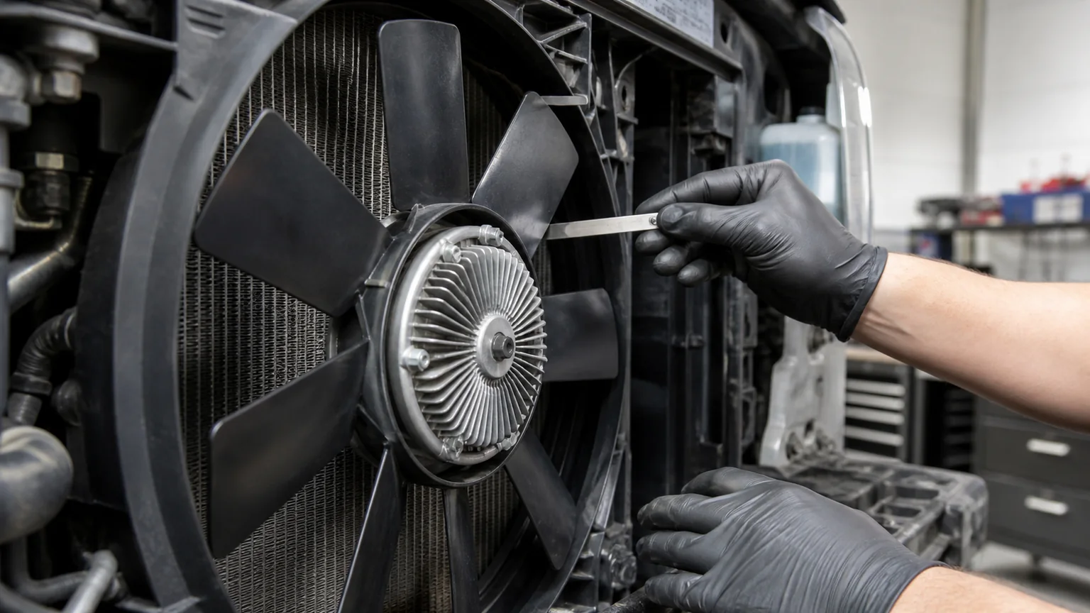
Measure the shortest distance from every blade tip or leading feature to the shroud around a full hand rotation, and from the nearest blade surface to the radiator core, hose, wiring and engine accessories. Rotate only when safe and permitted. Unequal shroud clearance may reveal a distorted blade, bent mount, sagged engine mount or mispositioned shroud.
Check how deeply the fan sits within the shroud opening. The correct position is application-specific; use the original arrangement and service data rather than a universal percentage. Confirm that the clutch front does not touch the radiator under engine movement and that the rear of the blade clears belts and hoses.
Inspect radiator mounts and the shroud. A loose radiator can move toward the fan. Missing lower cushions or an incorrectly latched upper support changes spacing. If the new radiator has a thicker core or different tank profile, validate the entire assembled clearance instead of approving each part independently.
Check minimum clearance through a complete manual rotation and consider engine movement, fan flex, radiator mounting and shroud position.
Installation controls that protect concentricity
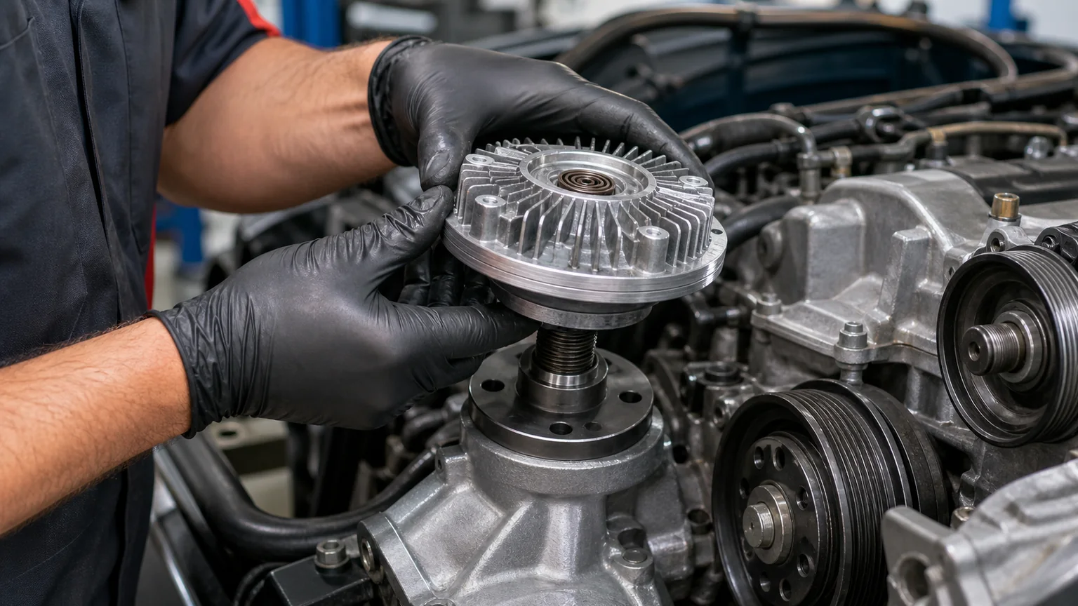
Clean the pump flange and pilot without removing metal. The clutch should seat squarely on the designed face. Dirt, a trapped washer or a burr can create runout. For threaded designs, start by hand in the correct direction and confirm several smooth turns before using a tool. Do not strike the clutch housing or use the fan blade as a lever.
Use specified fasteners and torque. Uneven tightening can distort a thin fan center or pull a flange off-axis. Tighten in a cross pattern where applicable, in progressive stages, while confirming that the pilot remains seated. Follow application instructions for thread locking, washers and reuse; generic additions can alter clamp load.
Keep the bi-metal spring and front face clean and unobstructed. Heavy paint, labels or covers can change thermal response. Route an electronic harness through the intended clips with slack for engine movement, away from the fan, belt, exhaust and sharp edges.
Before starting, rotate the assembly safely by hand through a full revolution and inspect from several angles. Reinstall the shroud and guards. A first start should be observed from a safe position, with tools and hoses removed from the engine bay. Stop immediately for contact, severe vibration or abnormal wobble.
Runout and vibration: what measurements can reveal
If the assembled fan appears to wobble, stop the engine. Inspect blade damage, seating faces, pilot fit, flange runout, water-pump bearing play and fastener clamp. A dial indicator can quantify runout when used by a trained technician on appropriate reference surfaces. Do not assume the clutch is the only rotating part capable of causing vibration.
A too-large pilot bore with bolts used as centering pins can place the clutch off-axis. A pilot that is too small prevents full seating. Incorrect spacers can tilt the blade. Worn water-pump bearings can allow movement that becomes more obvious with a new, tightly coupled clutch. Replace or correct the root cause before operating at speed.
A reproducible measurement sheet
Feature
Old unit
Candidate unit
How to describe it
Drive interface
Record
Record
Male/female thread or bolted flange; diameter, pitch and direction
Water-pump pilot
Record
Record
Male/female register diameter and depth
Pump pattern
Record
Record
Hole count, bolt circle, hole diameter and spacing
Fan pattern
Record
Record
Stud/hole count, bolt circle, thread and fan pilot
Working height
Record
Record
Pump mounting face to fan mounting face
Maximum envelope
Record
Record
Body diameter, front projection and connector projection
Rotation
Record
Record
Direction plus viewing position
Control
Record
Record
Thermal, non-thermal or electronic; connector/control details
Installed clearance
Record
Record
Radiator, shroud, hoses and accessories at closest points
Use one unit system throughout and include a scale in photographs. State whether a dimension is nominal, measured, or taken from a drawing. Repeated measurements by two people are valuable when a difference is close to the tool’s uncertainty.
Common matching errors
Buying by outer diameter: housing size does not establish pilot, height, rotation or calibration.
Calling adjacent-hole spacing the bolt circle: these are different dimensions.
Ignoring the pilot because the bolts enter: fasteners may not center the rotating assembly.
Using “clockwise” without a viewpoint: the same assembly appears opposite from the other side.
Assuming thread direction proves operating rotation: thread, drive and internal calibration need separate confirmation.
Measuring overall height across a spring or connector: functional mounting height must use defined faces.
Forcing the fan over a near-match pattern: stressed or off-center blades can fail.
Reusing a cracked blade: a new clutch does not make damaged rotating hardware safe.
Checking clearance before the shroud and mounts are secured: final geometry can be different.
Approving an electronic clutch by connector appearance: pinout and control strategy may differ.
What to send a supplier
Send the OE number, vehicle and engine details, old-unit label, clear front/back/side photographs, drive interface, water-pump pilot or bolt pattern, fan pattern, defined working height, maximum diameter, rotation with viewpoint, fan details and control type. For an electronic clutch, include connector face, wire count and harness length without applying test voltage. State the required quantity and destination.
Brand or application collections such as fan clutches for Volvo applications and fan clutches for Iveco applications narrow the search, but engine and OE confirmation remain decisive. If the vehicle has been modified, include measurements of the actual installed stack and explain the modification.
Final fitment checklist
For batch purchasing, approve a physical golden sample only after its measured record agrees with the application evidence. Keep that sample protected and use controlled gauges for incoming comparison. A golden sample does not replace supplier change notification: a revised bearing, connector, housing, calibration or included adapter can affect function even when the main dimensions remain unchanged. Require the label and revision to stay traceable to the inspection result.
OE and application data support the selected clutch.
Drive thread or pump flange, pitch, bolt circle and pilot match.
Fan bolt circle, thread, register and seating face match.
Working height and offset place the blade correctly in the shroud.
Drive rotation, thread direction and clutch calibration are confirmed separately.
Thermal or electronic control type and electrical interface match.
The blade is undamaged and approved for the clutch and rotation.
Static clearances are measured through a complete hand rotation.
Engine mounts, radiator mounts and shroud are secure enough to preserve dynamic clearance.
Specified fasteners, tightening method and guards are used.
First operation shows no contact, abnormal wobble or severe vibration.
Key conclusion: fan-clutch dimensions are most useful as a rejection and verification system. Pilot or thread, both mounting patterns, working height, rotation, control type and installed clearance must agree as a set. When one critical interface is uncertain, do not machine, slot or force the parts to fit; obtain an application drawing or a correctly matched unit.