English
Views: 0 Author: Site Editor Publish Time: 2026-09-14 Origin: Site
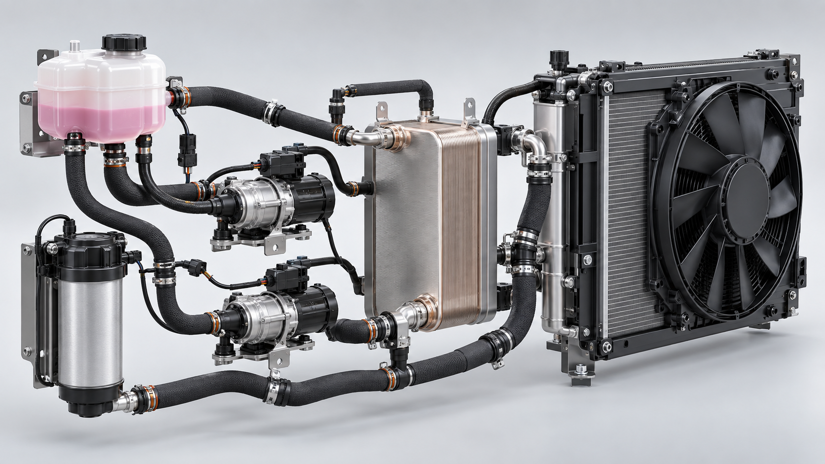
A fuel-cell stack cooling package must control stack temperature and temperature spread while preserving coolant electrical properties, low pressure drop, gas separation, cleanliness, corrosion compatibility, pump margin, radiator and fan capacity, heat-recovery modes, freeze protection, diagnostics, and safe fault response. A conventional engine radiator package cannot be assumed suitable merely because the heat load or hose size looks similar.
This guide is written for engineering teams, fleet operators, distributors, and aftermarket buyers evaluating emerging thermal products. It connects the new architecture to familiar sourcing controls used for a radiator, cooling fan, and heavy-duty thermal system, while keeping high-voltage, software, and battery or fuel-cell boundaries explicit.
Primary product context is available from Modine fuel-cell stack cooling package overview, MAHLE commercial-vehicle fuel-cell thermal products, SAE J3193 fuel-cell vehicle thermal management. Supplier-specific ratings and architectures are identified as such; they should not be copied into another platform specification without validation.
New thermal components should be identified as complete mechanical, fluid, electrical, and control systems.
Stack efficiency, allowable temperature, warm-up, transient load, humidity management, and degradation create a specific thermal problem. Heat must be rejected during high power, but controlled warm-up and uniformity also matter. Commercial vehicles add long grades, stationary power, and high ambient.
Use stack-supplier heat maps and limits across beginning and end of life. Include pumps, converters, air compressor, humidification, and other balance-of-plant heat where the architecture assigns them to connected loops.
Coolant near energized stack plates may require controlled electrical conductivity. Ions enter from water, inhibitors, metals, hoses, sealants, contamination, and aging. “Deionized water” at fill does not guarantee stable in-service conductivity.
Specify approved coolant, initial and operating conductivity limits, sampling method, sensor conditions, temperature compensation, and service interval. Follow the stack maker's chemistry; low conductivity must coexist with corrosion and freeze protection.
A deionization filter or ion-exchange cartridge can help manage conductivity, but its capacity depends on contamination load, coolant volume, temperature, materials, and service. Position and flow must allow effective treatment without unacceptable restriction.
Monitor conductivity trends and differential pressure where appropriate. A cartridge replacement schedule should come from validated data, not a universal calendar.
Total pump flow can look correct while internal branches receive uneven flow. Manifolds, stack passages, bypasses, filters, heat exchangers, hoses, and valves create resistance. Gas pockets can further reduce local cooling.
Model and measure branch flow or use temperatures to validate distribution. Define fill, degassing, reservoir, venting, and pump inlet conditions for all vehicle grades and accelerations.
Fuel-cell vehicle efficiency is affected by pump and fan power. Compare loop pressure drop at actual coolant viscosity and temperature over the operating range. Cold-start viscosity can dominate.
Select pumps at the system curve with margin for aging and filters, but avoid unnecessary continuous power. Control can vary flow with stack demand while respecting minimums.
Fuel-cell coolant temperature may leave less difference to hot ambient air than a combustion engine radiator enjoys. This can require larger heat exchangers, higher airflow, or careful airflow management. Face area alone does not establish capacity.
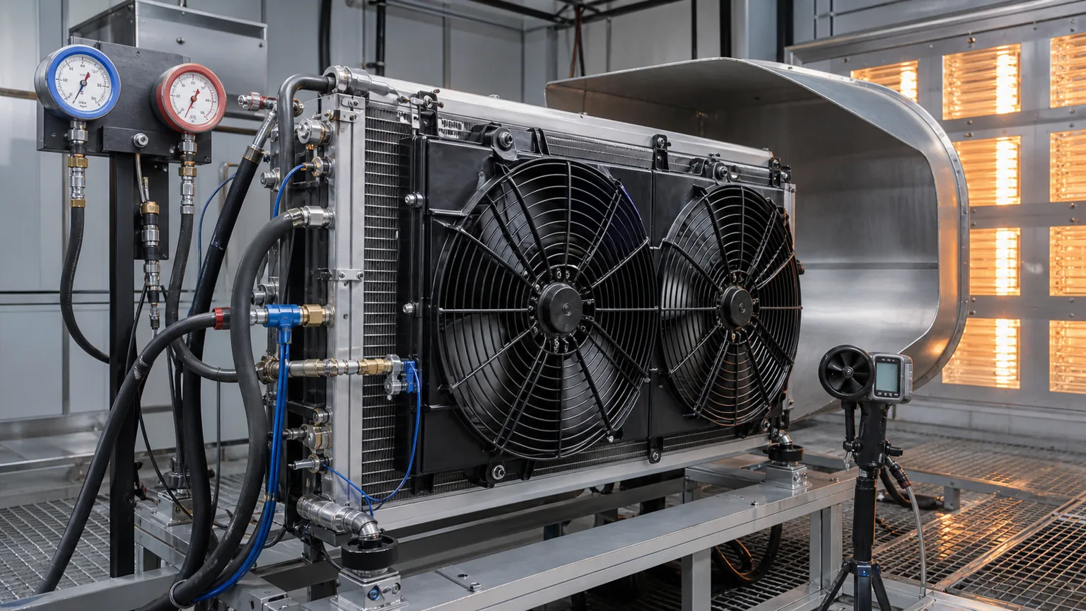
Compare heat rejection and coolant/air pressure drop at matched conditions. Include grille, filters, adjacent cores, fan curve, recirculation, altitude, and contamination.
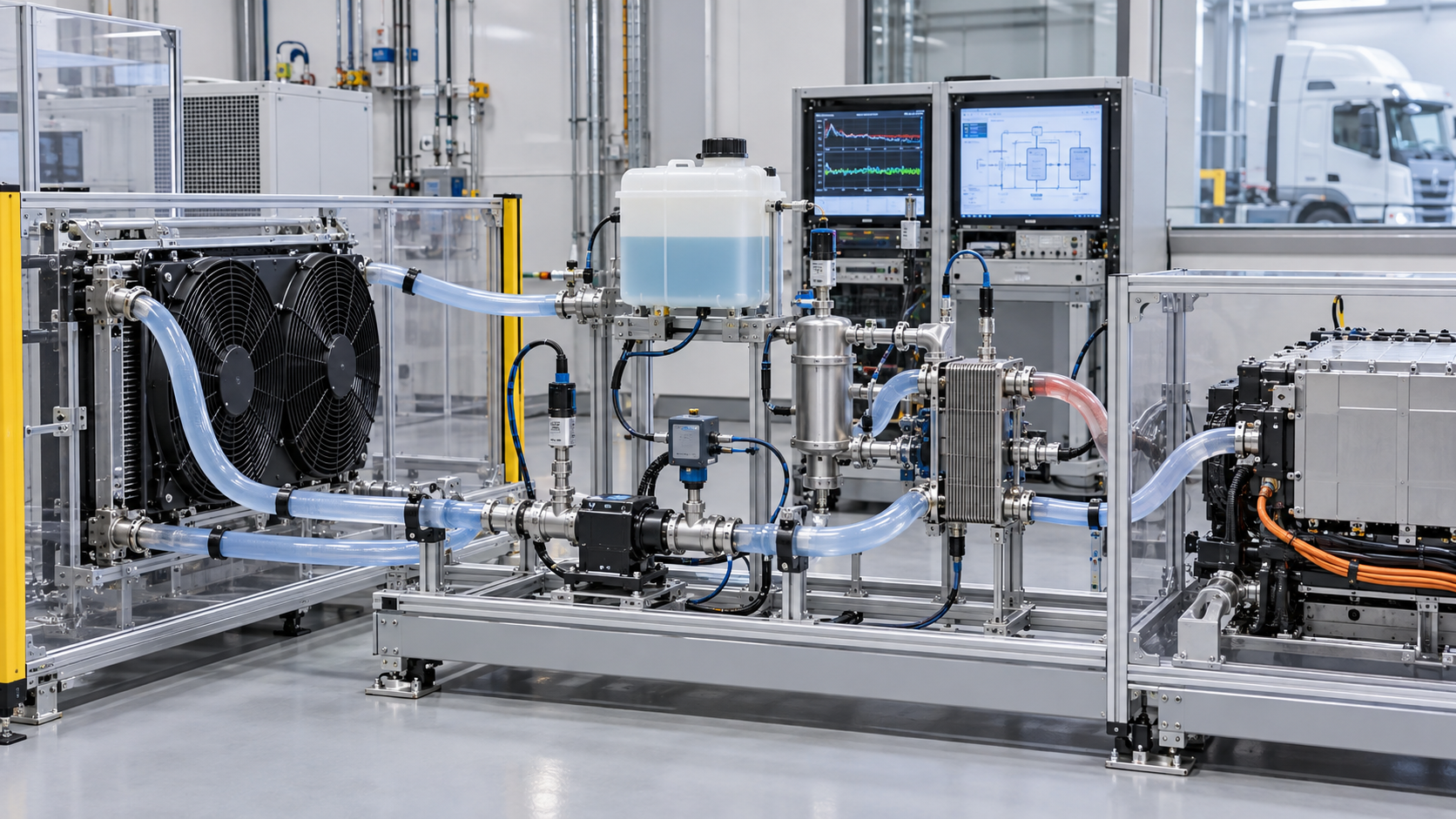
Bench validation must reproduce the relevant boundary conditions and record all interacting variables.
Large electric fans may use low or high voltage and controlled speed. Specify airflow at static pressure, power, noise, direction, shroud, connectors, messages, diagnostics, derating, and environment. Free-air data is insufficient.
Predictive control can use route, grade, load, ambient, stack demand, and thermal state to prepare airflow or coolant flow. A control claim should identify inputs, constraints, fail-safe behavior, and demonstrated benefit.
Stack heat can support cabin heating, battery warming, or other consumers through water-to-water heat exchangers and valves. MAHLE publicly discusses transferring fuel-cell coolant heat to a powertrain coolant loop. The exact architecture is vehicle-specific.
Map every valve and pump state and prevent one consumer from violating stack limits. Validate simultaneous demands, cold start, defrost, low stack load, and faulted valves.
Entrained gas reduces pump performance and heat transfer and can create local hot regions. Reservoir, deaeration, line routing, fill points, vents, and pump placement must work across vehicle orientation and transient flow.
Validate service filling and bleeding with production hoses. A laboratory rig with convenient transparent high points can hide vehicle packaging problems.
Every wetted metal, polymer, elastomer, coating, adhesive, and joining residue can contribute ions or degradation. Particulate debris can block stack passages and filters. Define both chemical and particulate cleanliness.
Qualification should use the full material set and approved coolant through thermal aging and electrical conditions. Keep ports sealed, dry components appropriately, and segregate tools from conventional coolant loops.
Coolant freeze protection, stack water management, heater power, pump startup, valve position, and warm-up determine whether the vehicle can start safely in cold conditions. Long storage can change fluid distribution and sensor state.
Test cold soak, repeated freeze-thaw where specified, interrupted warm-up, low auxiliary battery, and safe shutdown. Do not improvise drain or antifreeze changes outside the fuel-cell maker's procedure.
Log coolant inlet and outlet temperatures, flow or pump state, pressures, conductivity, fan and pump command/feedback, reservoir level, valve state, stack power, ambient, and faults. Define limp-home or shutdown boundaries.
Fleet troubleshooting should distinguish blocked radiator, weak fan, pump cavitation, gas, expired deionizer, wrong coolant, sensor drift, valve leakage, and stack-side problems.
Layer | Evidence to retain | Approval question |
|---|---|---|
Application | Vehicle or machine, architecture, duty, environment, revision | Does the evidence describe the actual platform? |
Hardware | Drawing, interfaces, materials, dimensions, labels, batch | Does the product fit and survive the physical system? |
Hydraulic or refrigerant | Fluids, flows, pressure drop, capacity, leak and cleanliness results | Does it move and transfer heat without contamination? |
Electrical | Voltage window, current or power, isolation, connectors, protection | Is it electrically safe and compatible in all states? |
Control | Messages, signals, firmware, diagnostics, fault responses | Can the vehicle command and verify the intended function? |
Durability | Thermal cycles, vibration, corrosion, environment, aging | Does performance remain after representative exposure? |
Production | End-of-line tests, capability, traceability, change notice | Will repeat orders match the approved sample? |
A prototype truck holds stack temperature during a warm-weather grade, so the radiator and fan appear successful. After durability accumulation, the conductivity sensor trends upward and the deionization cartridge reaches capacity much earlier than expected. Replacing the radiator would not address the problem.
Material review finds that hose and seal extracts, fill-tool contamination, and a brazed component cleaning residue contribute ions. The loop met thermal capacity but failed the electrical-chemistry objective. The team adds wetted-material screening, final-rinse control, dedicated service tools, incoming coolant checks, and a conductivity trend acceptance.
The corrected package is validated for heat rejection, pressure drop, pump and fan power, conductivity over aging, corrosion, gas separation, heat recovery, and fault response. Fuel-cell thermal approval is multidisciplinary by definition.
Obtain stack thermal, flow, pressure, conductivity, temperature-spread, and degradation limits.
Define vehicle duty, altitude, ambient, grades, stationary power, heat recovery, cold start, and storage.
Freeze approved coolant and every wetted material, cleanliness, fill, and service control.
Model loop pressure drop, flow distribution, gas separation, radiator approach, fan and pump operating points.
Map heat-recovery and rejection modes with valves, pumps, sensors, and controllers.
Bench-test thermal performance, chemistry, conductivity, flow, pressure drop, controls, and faults.
Run aging, corrosion, vibration, shock, sealing, freeze, thermal cycling, altitude, dust, and high-ambient validation.
Validate the complete vehicle during transients, grades, idle, cold start, and simultaneous heat demands.
Approve diagnostics, service intervals, traceability, predictive-control updates, and change notification.
Run a formal review after each layer. A visually correct sample should not advance if its software, fluid, safety, or duty evidence is unresolved. Deviations need named owners and closure criteria rather than informal promises.
Interfaces, software, ports, and traceability belong in the approval record.
Send the platform, annual volume, development phase, target market, duty cycle, ambient and altitude range, heat loads, electrical architecture, networks, fluids, packaging envelope, mounts, ports, sensors, safety requirements, standards, validation responsibility, sample stages, production timing, service concept, and change-control expectations. Mark confidential data and use controlled revisions.
Ask the supplier to distinguish available product, configurable family, and new engineering. Request the exact tested configuration and conditions. Do not treat a promotional product-family range as a commitment that one SKU covers the full range. For early concepts, agree which values are targets and which are demonstrated results.
Commercial comparison should include engineering, tooling, samples, validation, software support, warranty evidence, service parts, lead time, quality response, and lifecycle changes. Unit price alone cannot represent the risk of a safety-related integrated thermal component.
Verify labels, hardware and software revision, connectors, ports, caps, seals, mounts, visible damage, moisture protection, and traceability at receiving. Use risk-based sampling for dimensions, leak, insulation, communication, or functional tests. Keep new or revised lots quarantined until required evidence passes.
Require written notice before changes to materials, wetted components, geometry, tooling, joining, electronics, semiconductors, motor, sensors, firmware, communication, manufacturing plant, end-of-line testing, or packaging. Decide which analysis, bench tests, and vehicle tests must be repeated. Retain representative samples and data for each approved revision.
Selecting by nominal voltage or headline capacity alone
Assuming physical connectors guarantee electrical or digital compatibility
Comparing thermal figures at different boundary conditions
Ignoring pressure drop, pump or fan power, and control derating
Testing one operating mode while the product serves several modes
Using passenger-car evidence for heavy-duty or off-highway duty without validation
Dropping software and diagnostic revisions from the parts record
Approving a prototype without production end-of-line and change controls
Each shortcut substitutes a visible attribute for a system requirement. When information is missing, document the uncertainty and stop before energizing, charging, filling, or ordering production quantities.
Only after architecture, ports, internal function, fluids, pressure class, voltage, control, software, safety, mounts, and performance are confirmed. Appearance can start identification but cannot finish it.
No. They show capability boundaries. Approval requires the exact SKU or configuration, test conditions, application, interfaces, and documented limitations.
Only qualified teams with appropriate isolated equipment, procedures, safety controls, and technical data should do so. Otherwise use authorized test and service channels.
Preserve identity and software, operating mode, commands and feedback, voltages, currents, flows, pressures, temperatures, faults, fluids, installation images, and the timeline leading to the event.
Follow the vehicle or system maker's service boundary. Integrated products may contain non-serviceable or calibrated assemblies; unauthorized disassembly can create safety, contamination, and warranty risk.
Assign approved suppliers and specifications for coolant, make-up fluid, hoses, seals, reservoirs, filters, heat exchangers, and cleaning agents. Define sample containers and a temperature-compensated measurement method. Take baselines from fresh fluid, filled system, initial operation, durability intervals, and field service. Trend values rather than waiting for one limit crossing.
When conductivity rises, investigate recent service, top-up fluid, tool sharing, cartridge condition, material changes, corrosion, leaks between loops, and sensor calibration. Replacing the deionizer repeatedly can hide the source. Retained coolant and material samples allow laboratory confirmation.
Run stack cooling while cabin heating, battery warming, defrost, and powertrain loops request heat in different combinations. Verify valve leakage and unintended natural circulation when a branch is “closed.” Measure stack inlet and outlet, consumer inlet and outlet, flows, pump power, heat transferred, cabin or battery response, and controller priorities.
Test low stack power, high cabin demand, rapid acceleration, charger connection, and a faulted heat-recovery valve. The controller must protect the stack even if comfort or energy recovery is temporarily reduced. Explain that priority to operators so a protection event is not misdiagnosed as weak heater hardware.
Route and grade prediction can pre-cool or pre-position pumps and fans before a known climb, and charging information can prepare the loop for stationary heat. The benefit depends on accurate inputs and real component authority. Log the forecast, planned action, actual route, thermal response, and energy use to demonstrate value.
If connectivity, positioning, or prediction fails, the vehicle must remain safe on local temperature, flow, pressure, and power signals. Validate stale or incorrect predictions, route changes, sensor drift, and component derating. A sophisticated optimizer cannot replace physical protection limits.
A fuel-cell stack cooling package must control stack temperature and temperature spread while preserving coolant electrical properties, low pressure drop, gas separation, cleanliness, corrosion compatibility, pump margin, radiator and fan capacity, heat-recovery modes, freeze protection, diagnostics, and safe fault response. A conventional engine radiator package cannot be assumed suitable merely because the heat load or hose size looks similar. The right buying decision connects component evidence to the complete vehicle or machine duty and retains enough traceability to manage later changes.
For an Elecdura sourcing review, send the platform, part and software numbers, diagrams, labels, interfaces, quantities, destination, and required validation. Early clarity helps determine whether the request is a catalog match, a controlled equivalent, or a new engineering program.
Confirm assembly and software number, stack application, coolant specification, cleanliness state, shipping fill or dry condition, sealed ports, pump and fan identities, reservoir and deaeration components, deionization cartridge, sensors, valves, heat exchangers, mounts, harnesses, and traceability. Protect the module from conventional shop coolant, dirty funnels, and shared hoses. One contaminated fill tool can invalidate the conductivity plan.
Use controlled fixtures to verify leak integrity of each loop, valve state, pump and fan communication, sensor plausibility, low-voltage and high-voltage interfaces where present, and safe shipping damage inspection. Functional tests should not introduce unapproved water or test fluid that remains inside. Record draining and drying after any wet test.
Packaging must support full fluid-system mass assumptions, protect radiator fins and fan blades, restrain pumps and heavy filters, cap every port, and prevent vibration loads from concentrating at brazed pipes. Shock indicators can assist but do not replace inspection. Quarantine damaged crates until pressure, electrical, and alignment risks are evaluated.
If conductivity or corrosion is involved, take clean sealed samples from defined locations and record temperature, instrument, calibration, service history, top-ups, and cartridge age. Do not pour the sample into an ordinary coolant bottle. Retain failed filters, seals, hoses, and labels. Thermal data without chemical evidence cannot resolve a fuel-cell coolant complaint.
Preserve a comparison sample of unused approved coolant and, when possible, a sample upstream and downstream of the treatment component. Note whether the stack was hot, cold, operating, or recently shut down. Conductivity, ion analysis, corrosion products, particles, and fluid appearance can point to different sources, but results are meaningful only when sample handling and locations are controlled.