English
Views: 0 Author: Elecdura Publish Time: 2026-08-13 Origin: Site
Many application-specific radiator fan control modules are plug-and-play and require no coding. Others are part of an intelligent fan assembly or vehicle network and may require configuration, adaptation, calibration/software work, or a guided post-install procedure. Sometimes the replacement module needs no programming, but the engine or HVAC controller needs a software update. The requirement must come from VIN-specific service information and the exact OE part/supersession—not from the connector shape or a generic internet answer.
Before asking what to program, confirm that the part is correct and the original diagnosis is valid. A module cannot be coded into the wrong voltage, wattage, pinout, communication protocol, fan count, or motor design. Buyers can compare application-specific units in Elecdura's fan control module range, then verify the complete OE configuration and service procedure.
Action | What it means | Typical trigger |
|---|---|---|
No programming | Install correct part and verify operation | Application-specific plug-and-play module |
Clear DTCs / run output test | Remove stored faults and command the fan | Repair completed with no configuration change |
Basic setting or adaptation | Teach or initialize a function/value | Vehicle-specific service procedure |
Coding/configuration | Set vehicle-specific options or transfer data | Programmable module or intelligent assembly |
Calibration/software update | Flash revised control software | OEM bulletin, supersession, or control issue |
These terms are not synonyms. A repair order that says only “program fan module” is incomplete. Record which controller is addressed, which function is performed, which software/calibration applies, and whether the replacement hardware itself stores configuration.
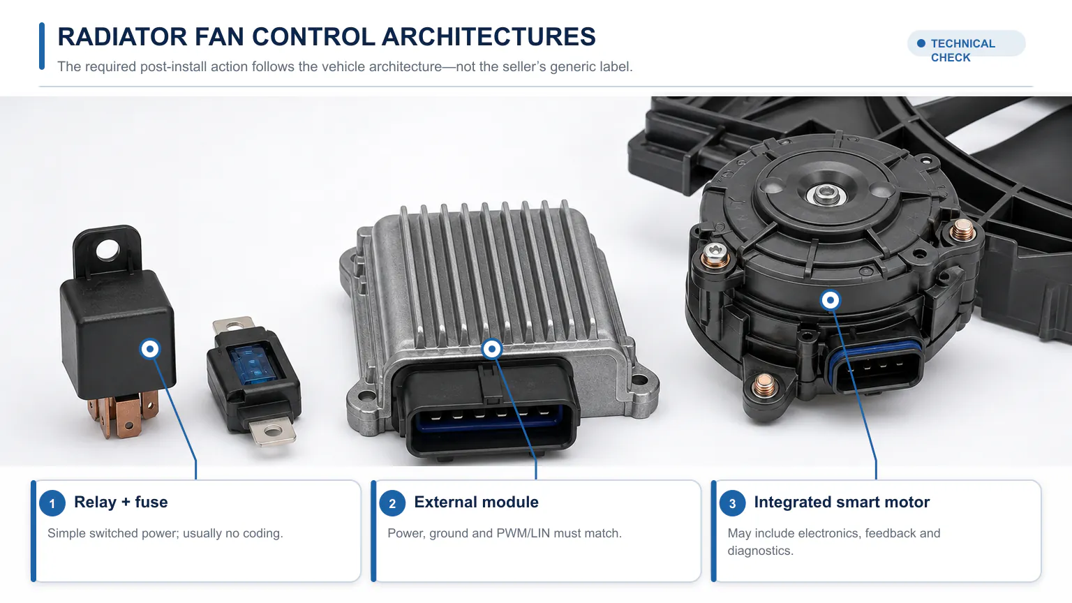
Fan systems range from simple switched circuits to externally controlled or integrated intelligent motors.
An older or simple system uses one or more relays to switch battery power to the motor. Two-speed systems may use a resistor or series/parallel relay arrangement. The relay or resistor is normally not programmable. Diagnosis focuses on fuses, relay command, contacts, wiring, resistor, motors, sensors, and ECU output.
An electronic module receives battery power and ground plus a pulse-width-modulated command from the ECU. It controls motor power to vary speed. Many aftermarket modules of this type are application-specific and plug-and-play; Gates, for example, markets replacement fan modules as exact-fit plug-and-play parts for listed applications. The duty signal and electrical load still must match.
A networked fan can receive a digital LIN command and may report speed, temperature, or faults. The module can be integrated with the motor. Correct communication protocol, addressing, software expectations, and part variant matter. A visually similar PWM unit cannot replace a LIN fan, and a LIN communication fault may lie in wiring or a master controller.
Brushless motors contain commutation and power electronics. The service part may be the complete motor or fan assembly, not a small external module. It may be delivered preconfigured for the application or require a vehicle procedure. Treat the motor and controller as an engineered pair.
Some vehicles package two motors, shared electronics, wiring, and shroud as one module. Other vehicles service each component. A complete-module replacement requirement is vehicle-specific. Do not infer it from the number of fans.
Connector shape alone cannot confirm a fan module; protocol, load and assembly variant must also match.
Programming cannot correct these mismatches:
OE number and supersession: confirm VIN and production-date applicability.
System voltage and motor power: 12/24 V, wattage/current, and fan load.
Connector and pin function: keying, terminal size, power/ground, PWM/LIN, feedback.
Control protocol: relay, analog/PWM frequency and polarity, LIN version/message expectations, or integrated control.
Fan configuration: one/two motors, diameter, rotation, blade, shroud, and airflow.
Thermal and environmental design: heat sink, mounting, cooling airflow, water protection, and vibration.
Software/calibration identity: where the service part contains programmable data.
Ask the supplier for the manufacturer number and OE cross-reference, not merely “fits model.” Compare labels and connectors before installation. If the part supersedes the original, retrieve the bulletin or catalogue note explaining associated harness, coding, or software requirements.
A fan module is often blamed because the fan does not run, runs at full speed, or stores a control code. Begin with a complete fault record: symptoms, ambient, coolant temperature, A/C pressure, commanded speed, actual speed or feedback, network status, and all relevant DTCs.
Check coolant-temperature plausibility, A/C pressure, engine load, battery voltage, and any other input used by the vehicle. A sensor open circuit can drive fail-safe full speed. Use the scan tool to command fan stages or percentages and monitor whether the controller sends the expected command.
High-current modules need clean battery feeds and grounds. Inspect fuses, relay or power distribution, grounds, connectors, and wire gauge. Measure voltage drop while the fan is commanded. A corroded feed can make a good module reset or overheat; an unloaded voltage reading can hide the problem.
Use the wiring diagram and specified measurement points. For PWM, check frequency, duty cycle, voltage levels, and reference/ground with an oscilloscope. For LIN, check power/ground and physical-layer activity with suitable equipment, then use diagnostics for communication and data. Do not pierce sealed wires unnecessarily or short a data line with a test lamp.
A seized or high-current motor can destroy a replacement power module. Inspect bearings, blade contact, shroud, debris, connectors, and current. If the module is external and replaceable, prove that the motor load is within specification before connecting the new unit.
VIN-specific service information determines whether the required action is none, validation, adaptation, coding or a software update.
Identify VIN, production date, engine, A/C, and fan option.
Retrieve OE service information and parts supersession. Use a current source.
Confirm the fault with circuit and load testing. Save DTCs and data.
Classify the service part. Relay/resistor, external module, intelligent motor, or complete assembly.
Read installation instructions. Search specifically for programming, coding, adaptation, initialization, or software update.
Check diagnostic-tool coverage and power support. Programming may require a stable battery maintainer and online authorization.
Install only after part comparison. Protect connectors and heat-transfer surfaces.
Perform the exact required action. Do not run generic coding “just in case.”
Clear and rescan all relevant modules.
Validate all fan speeds and real thermal operation.
Gates describes its application-specific engine cooling fan modules as plug-and-play. That is useful evidence that many external replacement modules do not require programming when the correct part is installed. It does not prove that every module sold by every company is plug-and-play, or that no scan-tool validation is needed.
A plug-and-play module can still expose an upstream fault. If the ECU command is missing because of a sensor, wiring, software, or network issue, a new module will behave like the old one. If the motor draws excessive current, the new module may fail. “No coding required” is not the same as “no diagnosis required.”
Ford's module programming guide explains general operations such as Programmable Module Installation, reprogramming, and programmable parameters. It demonstrates that some vehicle modules store configuration and need data transfer. It does not identify every fan controller as a programmable Ford module; the VIN-specific tool menu and workshop manual must list the module.
A GM technical bulletin provides a vehicle-specific example where a cooling fan is reprogrammed through the engine control module. This illustrates a calibration action in the control chain, not proof that a replacement fan power module always stores software. Similarly, HELLA documents a Seat/VW case in which an ECU software error could cause continuous fan operation and the remedy involved an ECU update and, if necessary, fan control replacement.
These cases lead to the correct rule: determine which controller owns the behavior and which OEM action applies. Hardware replacement, ECU flash, coding, and adaptation can appear in the same repair ecosystem while addressing different causes.
Low system voltage, interrupted communication, incorrect VIN/session, wrong module selection, incompatible aftermarket hardware, lost configuration data, or an unsupported diagnostic tool can leave a vehicle with new faults. Follow programming prerequisites, including the specified battery support device, network connection, ignition state, key handling, and software level.
Keep hands and tools away from fans during any diagnostic or software procedure. OEM bulletins warn that radiator fans may start or run at high speed during updates. Secure the work area and do not rely on ignition-off as lockout.
Save original configuration or as-built data when the procedure requires it. Do not alter unrelated programmable parameters. Record old/new part numbers, software/calibration identifiers, tool/session results, DTCs, and post-repair tests.
Inspect connector seating, terminal lock, grounds, heat sink/contact surfaces, harness route, blade clearance, and shroud mounts.
Check battery and charging voltage.
Scan all related modules and resolve communication or configuration faults.
Run the specified coding/adaptation or confirm that none is required.
Command fan speeds and compare requested with actual/feedback.
Measure module supply voltage and motor current under load.
Verify airflow direction, noise, vibration, and no blade contact.
Warm the vehicle under controlled conditions to verify coolant-temperature regulation.
Operate A/C and verify pressure/fan response.
Perform a final scan and check for connector/module overheating.
For individual replacement, send VIN, OE number, original label, connector/pin photos, fan count and diameter, motor label, and DTC/diagnostic context. For wholesale, create fields for control type, protocol, frequency where applicable, voltage/wattage, heat sink/mount, connector, compatible motor/assembly, software/coding requirement, traceability, and change control.
Compare module-only options with Elecdura's radiator fan motors and complete fan assemblies. The purchasing system should show which components are separately serviceable and which applications require an integrated unit.
For sample approval, verify pin functions, command response across speed range, motor current/temperature, feedback or diagnostics, fault behavior, environmental sealing, fit/heat sinking, and application coding. An aftermarket supplier must notify the buyer before changing power electronics, firmware, protocol, connector, housing, or sub-supplier.
Many catalogue errors begin when every rectangular device near a fan is stored under the same description. Build a structured record rather than a free-text title. At minimum, store the vehicle and production range, OE and supersession numbers, supplier number, module location, fan/motor association, voltage and rated load, connector count and pin functions, control input, feedback output, network protocol, cooling/heat-sink requirements, and whether software or coding is applicable.
Record the service level: module only, module plus harness, motor/controller, single fan assembly, or complete dual assembly. Photograph both sides and every connector beside a scale. Where a module is cooled by mounting to a shroud or heat sink, include the contact surface, fastener torque, and thermal interface material in instructions. Selling the correct electronics without the required thermal installation can cause repeat failure.
Separate “programming required” into controlled values: none, DTC clear/output test, adaptation/basic setting, coding/configuration, flash/update, or consult VIN-specific procedure. A yes/no field invites incorrect assumptions. Link each value to a source and revision date, and force manual review when an OE supersession changes.
For fleets, use a standard intake so intermittent cases are not reduced to “fan module bad.” Record vehicle identity, mileage/hours, ambient, road speed, coolant and transmission temperature, A/C status, whether the fan was off/full/intermittent, battery condition, recent jump-start or charging event, washing/water exposure, previous repairs, and all DTC freeze-frame data.
Compare an affected vehicle with a known-good identical configuration using the same commanded speeds. Measure power and ground voltage drop, control waveform or network activity, motor current, and actual fan speed. Swap testing can be risky: a seized motor can damage a known-good module, and a configured module can create new faults in another vehicle. Use it only when the manufacturer procedure allows it and the load has already been verified.
Trend replacements by OE part, supplier batch, vehicle group, failure mode, and root cause. If modules fail mainly after fan motor current rises, revise the repair rule to test or replace the load. If failures cluster after pressure washing, improve connector sealing or washing procedure. If no-fault-found returns cluster around one DTC, improve diagnosis and catalogue notes rather than changing suppliers immediately.
A fan power module can dissipate substantial heat. Some units use the fan's airflow, an aluminum base, the shroud, or a dedicated heat sink. Corrosion, dirt, missing thermal compound, warped mounting, loose fasteners, or a substitute plastic housing can raise semiconductor temperature even when electrical commands are correct.
Inspect the mounting surface and preserve the specified heat-transfer path. Do not coat, insulate, or relocate the module without engineering approval. Confirm that the fan actually moves cooling air over the electronics at low command and after hot soak. A replacement that survives a brief output test can fail later if the heat sink is not installed correctly.
During validation, monitor case temperature if the service or supplier method provides a limit. Test at high ambient and sustained fan load, not only with a cold module. Check connector temperature rise as well: terminal resistance generates localized heat that can look like an internal electronic failure.
Recheck part number, fuses, power/ground under load, command signal/network, motor, pinout, connector, and required initialization. Confirm the system is requesting fan operation.
Full speed may be a fail-safe for missing temperature/pressure/communication data, invalid coding, incompatible protocol, ECU software, or a module fault. Read data and network codes before condemning the replacement.
The part may not be a separately addressable module. It may be controlled through the ECU by PWM, or the tool/vehicle configuration may not support direct access. Verify the architecture and service procedure rather than forcing a generic module session.
Measure motor current, inspect for seizure/contact, verify cooling/heat sinking, repair connector resistance and water entry, check overvoltage, and confirm the correct power rating. Preserve the failed unit and batch information for analysis.
Yes, many application-specific units are. It must match the exact OE hardware and control requirements. Confirm the supplier's application instructions and vehicle procedure.
It depends on architecture, part status, configuration/security, condition, and vehicle rules. Used power electronics may contain wear, heat or moisture damage and unknown history. Check whether configuration is stored and whether the OEM permits reuse.
No. Clearing DTCs deletes stored diagnostic information. Programming changes software or data; coding/configuration sets options; adaptation/basic setting initializes learned or operating values.
No. It may clear volatile states or create additional initialization needs, but it does not install required software or correct coding. Follow the service procedure.
Sometimes, but many are preconfigured plug-and-play. Intelligent networked assemblies and certain vehicle procedures can require post-install actions. Check the VIN and exact part.
The safest answer is conditional: many fan modules need no programming; some repairs require adaptation, coding, or software; and some software actions occur in another controller. Prove the failure, identify the architecture, match OE hardware, and read VIN-specific service information before installation.
For a module, motor, or complete fan quotation, send the OE list, labels, connectors, control architecture, annual quantity, and required validation through the Elecdura contact page. A precise application response will state whether the supplied part is plug-and-play or requires a defined post-install procedure.