English
Views: 0 Author: Elecdura Publish Time: 2026-08-07 Origin: Elecdura
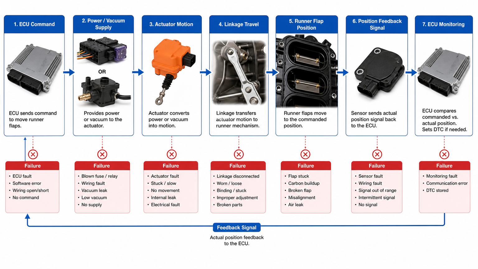
Intake manifold runner control valve symptoms usually appear when the commanded runner position and the actual airflow path no longer agree. The engine may lose low-speed torque, feel flat at higher rpm, hesitate during a transition, idle unevenly, or store codes such as P2004, P2006, P2008, or a manufacturer-specific position fault. None of these observations proves that the complete intake manifold is defective. The same code family can be produced by a broken linkage, a leaking vacuum hose, a failed solenoid, missing power or ground, a position-sensor circuit, carbon-bound flaps, or an actuator that has lost its learned stops.
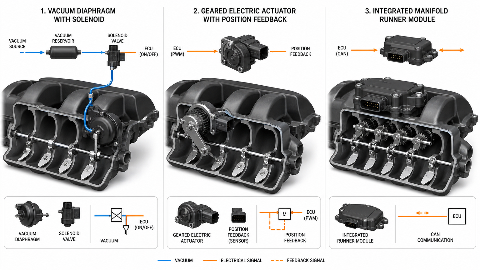
The correct test begins by identifying the runner-control architecture. Some engine parts use vacuum diaphragms and switching solenoids; others use geared electric motors with internal feedback; some integrate the shaft, flaps, stops, actuator, and sensor into the intake manifold assembly. A test written for one layout can damage or misdiagnose another.
Variable intake runners do not simply open and close air like a throttle. They change the effective path, cross-section, or swirl behavior of the intake charge so cylinder filling is better across different speed and load ranges. A long or restricted path may improve air velocity and torque at lower speed; a shorter or less restricted path may support airflow at higher speed. Other systems use swirl or tumble flaps to improve mixture preparation and emissions under selected conditions.
Because the operating goal differs, a runner that is normally open on one engine may be normally closed on another. Spring return direction is not a universal diagnostic rule. Use the correct wiring diagram, vacuum routing, scan-tool description, and service information for the engine code and market version.
Architecture | Primary inputs | Common fault points | Best first test |
|---|---|---|---|
Vacuum diaphragm | Vacuum supply and solenoid command | Split hose, leaking diaphragm, stuck linkage, failed solenoid | Verify source vacuum, then apply controlled vacuum to actuator |
Electric actuator with feedback | Power, ground, command, position signal | Gear damage, motor fault, wiring, sensor, lost adaptation | Compare commanded and actual position while checking supply |
Integrated manifold module | Actuator plus internal shaft and stops | Worn shaft, detached lever, carbon binding, housing damage | Observe full mechanism travel and stop repeatability |
Swirl flap by bank | Bank-specific actuator or linkage | One bank stuck, sensor correlation, unequal deposits | Compare bank data and physical motion under the same command |
A code is a test result recorded by the control module, not the name of the part to replace. "Stuck open" may mean that the feedback signal failed to reach the expected range after an open or close command. It can also mean the control module inferred the position from airflow, manifold pressure, or another plausibility check. Record the code, status, freeze-frame conditions, bank, engine speed, load, temperature, and whether it resets during a key-on self-test or only under load.
Generic P-code wording is not enough when the manufacturer uses a different bank convention or an actuator with an internal controller. Confirm whether the code refers to a circuit, range/performance, commanded position, stuck condition, or adaptation limit. This distinction decides whether to begin at the connector, the vacuum circuit, or the mechanical linkage.
A fixed runner position often reduces performance in the range that depends on the alternate path. Low-speed response may weaken when the runners remain in a high-flow position, while high-rpm breathing may suffer if the path stays restricted. A smooth but predictable torque change is more consistent with runner control than a random misfire, but ignition, fuel delivery, exhaust restriction, boost control, and valve timing can create similar complaints.
A loose external lever can rattle, stripped gears can click at the stop, and an actuator may cycle repeatedly when feedback never reaches the target. Locate the noise with safe listening methods and compare it with scan-tool commands. Do not place fingers near a linkage during an active test. A quiet actuator is not necessarily healthy; it may have no power, no command, a seized motor, or a disconnected mechanism.
Runner faults can alter cylinder filling, but a large lean fuel-trim correction at idle often points more directly to unmetered air. Check the intake gasket, PCV circuit, purge valve, brake-booster line, and cracked hoses. The separate guide to intake manifold replacement symptoms covers the broader assembly decision; the present test must establish runner-control evidence rather than using rough idle alone.
Scan every relevant module before clearing anything. Note pending, current, and history codes. Look for low-voltage events, throttle faults, manifold-pressure faults, communication issues, or actuator supply codes that could disable runner operation. Capture commanded runner position, actual position, duty cycle, manifold pressure, throttle angle, calculated load, fuel trims, and engine speed where supported.
If command changes but feedback does not, investigate power transmission, feedback, and mechanical motion. If neither command nor duty cycle changes, the system may be outside its enabling conditions or inhibited by another fault. If feedback changes without visible shaft motion, the sensor or linkage relationship may be wrong. Verify scan data against physical observation instead of accepting one data item in isolation.
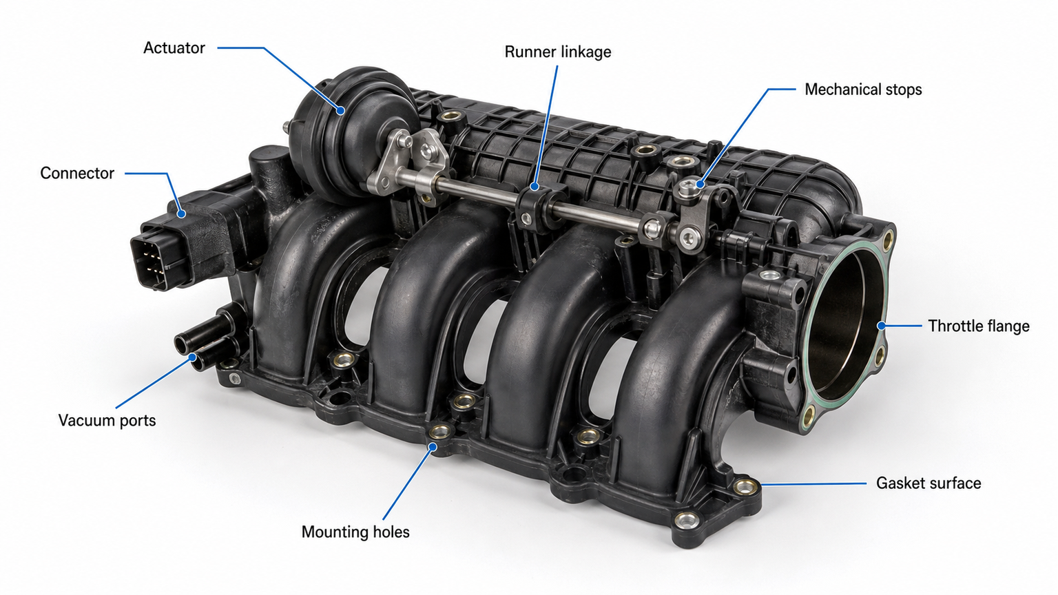
Locate the actuator, lever, shaft end, vacuum hose, solenoid, and connector. Check for a detached clip, cracked lever, missing stop, oil or water entry, rubbed wiring, broken lock, or previous adhesive repair. Move only those parts the service procedure permits. Plastic runner parts can become brittle with heat and age; forcing the shaft may turn a repairable actuator diagnosis into a complete manifold replacement.
Measure source vacuum at the specified condition. Then verify whether the switching solenoid passes or blocks vacuum when commanded. Apply controlled vacuum to the diaphragm with an appropriate hand pump and observe both movement and hold. A diaphragm that moves but will not hold vacuum is different from a linkage that will not move even with stable vacuum. Inspect check valves and reservoirs if the system loses control only under acceleration.
Direct vacuum may be useful as a controlled test, but continuous vacuum can lock the runners in the wrong position and hide the electrical or control fault. Verify solenoid resistance only against the correct specification and follow with a loaded circuit test, because a coil can measure plausibly while the connector or driver cannot carry current.
Identify every terminal from the wiring diagram: battery supply, ignition supply, ground, control, reference voltage, sensor return, or network connection. Back-probe only with approved tools. Confirm supply voltage and ground integrity under load, not only with the connector unplugged. A corroded terminal may show battery voltage on a high-impedance meter yet collapse when the motor operates.
Do not apply battery voltage to an unknown control or feedback terminal. Some actuators contain electronics and communicate digitally. Use an approved bidirectional test where available and observe current, position, and sound. If the procedure permits resistance testing, disconnect the required modules and respect temperature-dependent specifications.
Disconnecting the actuator from the shaft, when the manufacturer permits it, can reveal whether the motor drives normally without manifold load and whether the runner shaft moves smoothly through its allowed range. Heavy deposits can increase breakaway force, while worn gears may move an unloaded lever but stall when connected. Inspect for missing flap material or shaft wear; cleaning cannot restore a loose shaft or broken stop.
Some systems learn open and closed stops after battery disconnection, actuator replacement, manifold replacement, or software service. An adaptation failure can be the consequence of a sticking mechanism, incorrect part, low voltage, or feedback error. Repeating relearn procedures will not repair those conditions. Stabilize battery voltage and follow the exact key, temperature, and scan-tool requirements.
Fault | Expected evidence | Evidence against it |
|---|---|---|
Split vacuum hose | Low or absent actuator vacuum; actuator holds when tested directly | Stable correct vacuum at diaphragm during command |
Leaking diaphragm | Moves with vacuum but does not hold; no stable position | Vacuum holds and linkage reaches both stops |
Open motor circuit | Correct command and supply, no current or motion | Normal current and repeatable physical travel |
High-resistance connector | Voltage drop under load, heat discoloration, intermittent motion | Low loaded voltage drop at both power and ground |
Carbon-bound shaft | High effort, incomplete travel, actuator stall or adaptation failure | Smooth unloaded shaft through the specified range |
Broken linkage | Actuator moves but shaft or flaps do not follow | Positive coupled motion with no free play |
Position sensor fault | Motion visible but feedback jumps, drops out, or disagrees | Feedback follows motion smoothly and reaches learned limits |
The service boundary is determined by construction and damage. A separately cataloged vacuum diaphragm, solenoid, clip, or electric actuator may be replaced if the internal shaft and flaps are sound. A complete manifold is usually the safer scope when the shaft is worn, a flap is damaged, the stop is broken, the actuator mounting is cracked, internal contamination cannot be removed by an approved process, or the manufacturer does not service the failed part separately.
The failed component is available for the exact application and revision.
The runner shaft moves smoothly and has no unacceptable play.
The flaps, stops, housing, and actuator mounts are intact.
The replacement provides the correct connector, lever geometry, travel, and feedback range.
The required adaptation completes and commanded position agrees with actual position.
An integrated assembly avoids transferring a worn internal mechanism to a new actuator. It may also include seals, sensors, or mounting hardware, but contents vary by part number. Confirm whether the proposed unit includes the runner motor, position sensor, vacuum actuator, solenoid, gaskets, fuel-rail hardware, or other attachments. Never promise included parts from a representative photograph.
Runner-control fitment can change within the same model year and engine family. Match the OE number, vehicle identification data, engine code, market, emissions configuration, manifold material, port count, connector and pin layout, actuator orientation, vacuum-port arrangement, sensor provision, throttle-body flange, fuel-rail mounts, and runner linkage. Compare photographs from the same angles and confirm supersessions through an authoritative catalog.
For an aftermarket program, approve a sample using functional criteria rather than appearance alone. Verify connector retention, actuator travel, feedback stability where applicable, vacuum hold, stop repeatability, shaft free play, sealing-surface flatness, insert security, port cleanliness, and the included gasket set. Packaging must support the manifold without loading the runner lever, vacuum nipple, sensor, or throttle flange.
Send the OE reference, VIN-derived application data where appropriate, engine code, clear label and connector photos, actuator type, vacuum-port and linkage views, manifold front and rear views, the diagnostic result that identified the failed boundary, required quantity, destination, and packaging expectations. Use Elecdura's catalog downloads for range review and the contact page for an application-specific request.
Distributors serving mixed fleets should separate on-highway applications from off-highway applications. Duty cycle, filtration, vibration, connector sealing, and service access can change the practical failure pattern even where the control principle is similar. Related thermal components belong in the engine cooling range, but they should not be inserted into an IMRC diagnosis unless the evidence connects them.
If testing identifies only an external vacuum solenoid, the purchase specification should describe its port layout, electrical connector, coil/control requirements, bracket, and hose orientation. If the diaphragm leaks, record its rod length, end fitting, stroke, spring direction, mounting centers, and vacuum connection. If the internal shaft binds or a flap is loose, quote the complete intake manifold and define every transferred component. This boundary-first method prevents a general product inquiry from becoming an unverified promise that an actuator is included.
A superseded manifold may be correct only with updated software, a revised harness, a different gasket, or transferred hardware. Record both the original and replacement OE references and verify the supersession source. During sample approval, compare the actuator label, connector keying, mechanical stops, shaft direction, sensor response, and port sealing with the retained reference. These checks are more useful than relying on a broad aftermarket description.
Cap open ports without inserting loose material into the runners. Support the housing, not the actuator lever or vacuum nipple. Keep the unit clean and dry, and do not stack weight on plastic sealing flanges. A wholesale inspection plan should record carton condition, port caps, label traceability, included gaskets, connector protection, and free runner movement where the approved procedure permits it. Use the available catalogs to align reference data, then send unresolved application differences through the technical inquiry channel. If a customer is also sourcing cooling-system parts, keep those line items and their inspection standards separate from the intake-air assembly.
A fixed runner may mainly reduce performance or increase emissions, but a loose flap, broken linkage, severe air leak, or detached internal part can create greater risk. Diagnose promptly and follow the vehicle maker's guidance rather than assuming every runner code is equally safe.
P2004 commonly describes a runner stuck-open result. Confirm the bank, vacuum or electrical command, actual motion, linkage, feedback, and adaptation before deciding whether the actuator or manifold is responsible.
Cleaning may restore a mechanically sound shaft that is deposit-bound. It cannot repair worn pivots, broken flaps, stripped gears, cracked housings, failed sensors, or damaged wiring. Prevent debris from entering the engine.
Some vacuum and electric actuators are separate service parts; others are calibrated or supplied only with the manifold. Match the exact OE reference, lever geometry, connector, travel, and adaptation requirement.
Verify that codes do not reset, commanded and actual position follow correctly, both stops are reached without abnormal noise, fuel trims and drivability are appropriate, and the complaint does not return under the original operating conditions.
For runner-control replacement matching, send Elecdura the manifold OE number, engine application, connector and linkage photos, actuator architecture, vacuum-port layout, diagnostic evidence, included-parts requirement, and order quantity. These details determine whether the correct quotation is a separate actuator, a supporting control component, or a complete intake manifold rather than a visually similar but incompatible assembly.