English
Views: 0 Author: Site Editor Publish Time: 2026-09-14 Origin: Site
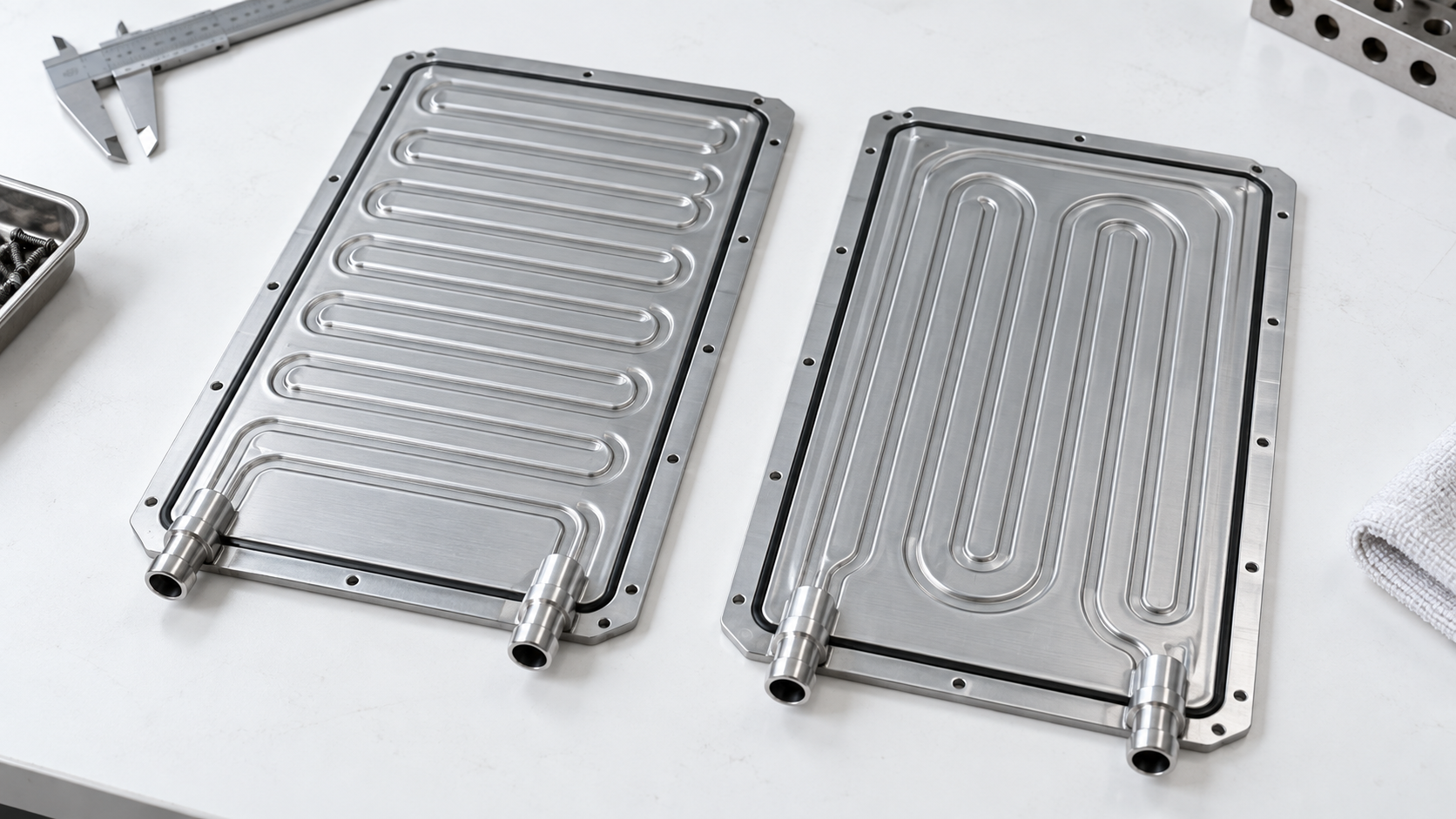
I-flow and U-flow describe how coolant is routed between the inlet and outlet, but neither is universally superior. Single- versus double-sided eCoolers describe how one or both broad faces exchange heat with cells or modules. Selection must balance temperature uniformity, pressure drop, pumping power, packaging, connection location, wall and joint durability, electrical isolation strategy, crash loads, manufacturing variation, cleanliness, and leak detection.
This guide is written for engineering teams, fleet operators, distributors, and aftermarket buyers evaluating emerging thermal products. It connects the new architecture to familiar sourcing controls used for a liquid cooler, off-highway application, and vehicle heat exchanger, while keeping high-voltage, software, and battery or fuel-cell boundaries explicit.
Primary product context is available from BorgWarner intercell eCooler information. Supplier-specific ratings and architectures are identified as such; they should not be copied into another platform specification without validation.
New thermal components should be identified as complete mechanical, fluid, electrical, and control systems.
An intercell cooler is placed between or closely integrated with cell or module structures so the coolant plate contacts heat-generating surfaces. The geometry can provide direct, compact heat removal but creates strict thickness, flatness, sealing, and electrical-clearance requirements. Battery architecture determines what “intercell” means.
BorgWarner publicly describes aluminum intercell eCoolers with I-flow and U-flow options, single- or double-sided cooling, and wall thickness of at least 0.3 mm for that product family. Those details are supplier-specific reference points, not universal minimums.
In a simplified I-flow plate, inlet and outlet are at opposite ends and coolant travels broadly across the plate. This can support straightforward manifolding and a long directional gradient. Channel distribution must prevent some paths from taking most of the flow.
The temperature rise along the flow direction may align with cell heat distribution or may amplify it. Simulation and measured cell-interface temperatures are needed. External port location can be decisive for pack assembly.
A U-flow route turns within the plate so inlet and outlet can sit near one end. This can simplify pack plumbing and service connections. The return leg also creates another opportunity to balance temperature distribution or recover heat from a neighboring region.
The turn, manifold, and parallel channels affect pressure loss and flow balance. A neat port layout is not proof of uniform cooling.
A single-sided plate transfers heat mainly through one face. It may suit cells or modules mounted on one side, reduce sealing and contact complexity, and simplify structural integration. The opposite face may connect to a carrier or insulation layer.
Contact pressure, gap filler, flatness, and local hot spots remain critical. A plate outlet temperature can look acceptable while poor contact leaves an individual cell hot.
A double-sided eCooler can exchange heat on both faces, potentially cooling adjacent cell rows or modules and improving packaging efficiency. It also creates two controlled contact interfaces and may face combined clamping loads.
Thickness variation, bulging under pressure, crash deformation, isolation, and service disassembly need validation. The design must prevent a coolant leak from creating an uncontrolled electrical path.
Channel length, hydraulic diameter, turns, manifolds, fittings, viscosity, coolant temperature, and flow determine pressure drop. Compare candidate plates at the required fluid and temperature over the full flow range. A water test at room temperature may not represent cold glycol mixture.
Add hoses, valves, filters, quick connectors, chillers, and other plates to the pump calculation. Parallel branches can distribute unevenly if resistance varies.
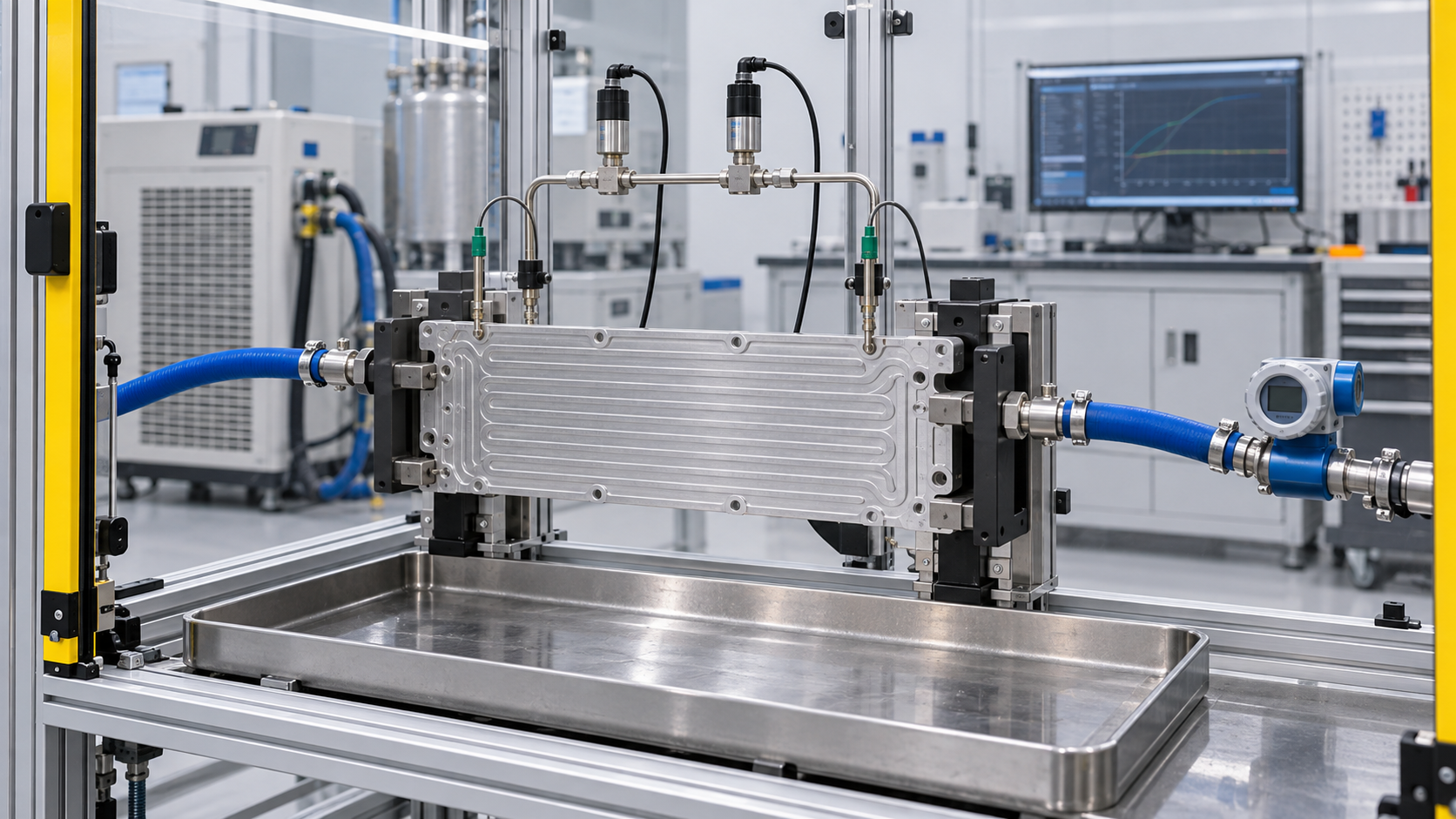
Bench validation must reproduce the relevant boundary conditions and record all interacting variables.
Average heat rejection does not prove that all cells remain within their temperature targets. Use a representative heat source and measure interface temperatures across the plate during steady and transient loads. Include coolant inlet temperature, flow, heat flux, contact material, compression, and ambient losses.
Look at maximum temperature and spread, not only outlet coolant temperature. Repeat with manufacturing tolerances and different orientations if trapped gas can affect channels.
Reducing wall thickness can improve thermal path and packaging but decreases margin against forming strain, pressure, fatigue, clamp load, and crash intrusion. Material temper, stamping depth, corner radii, joint design, and surface defects matter.
Validate proof or pressure cycling, vibration, thermal cycling, swelling, contact load, and crash-related deformation according to the pack design. Do not borrow a universal pressure.
End-of-line leak testing can detect gross and fine leakage under controlled conditions, but it does not prove durability. Define test medium, pressure, stabilization, temperature, allowable rate, fixture volume, calibration, and traceability. Test both the plate and final pack connections.
A process may combine forming inspection, joint monitoring, helium or gas testing, pressure decay, and coolant proof testing. Select methods based on defect size and production rate.
Particles can block small passages or valves and abrasive debris can damage pumps. Residue and moisture can alter coolant chemistry. Define particulate and chemical cleanliness, drying, sealed caps, and storage.
Material couples, coolant inhibitors, conductivity, and service contamination influence corrosion. Validate with the approved coolant and actual metals, gaskets, adhesives, and electrical environment.
Port diameter alone cannot approve a connection. Check bead or seal geometry, insertion depth, retention, hose load, clocking, assembly access, and tolerance stack. A port placed correctly in CAD may be unreachable after cells and busbars are installed.
Test connection loads and pressure while the plate is constrained as in the pack. Packaging caps should protect seals and keep passages dry.
Record alloy, temper, sheet thickness, channel geometry, forming tool, joining process, leak-test method, surface treatment, port supplier, and flatness. Small changes can alter both thermal and structural results.
Use production capability data and periodic destructive sectioning or audits where appropriate. Trace plates to cell modules and packs so a field issue can be contained.
Layer | Evidence to retain | Approval question |
|---|---|---|
Application | Vehicle or machine, architecture, duty, environment, revision | Does the evidence describe the actual platform? |
Hardware | Drawing, interfaces, materials, dimensions, labels, batch | Does the product fit and survive the physical system? |
Hydraulic or refrigerant | Fluids, flows, pressure drop, capacity, leak and cleanliness results | Does it move and transfer heat without contamination? |
Electrical | Voltage window, current or power, isolation, connectors, protection | Is it electrically safe and compatible in all states? |
Control | Messages, signals, firmware, diagnostics, fault responses | Can the vehicle command and verify the intended function? |
Durability | Thermal cycles, vibration, corrosion, environment, aging | Does performance remain after representative exposure? |
Production | End-of-line tests, capability, traceability, change notice | Will repeat orders match the approved sample? |
A U-flow candidate shows lower total pressure drop than the current I-flow plate at warm coolant. Procurement expects lower pump power and approves a prototype. In the representative module test, several cells near the internal turn run warmer during fast charging.
Flow visualization and surface thermography reveal that the U-turn manifold favors outer channels while contact compression is lower near the center. The low aggregate pressure drop hides maldistribution and an interface problem. Neither U-flow nor low pressure drop is inherently the cause; the detailed geometry and assembly create the result.
The supplier revises the manifold and contact support, then repeats cold and warm coolant tests, transient charging, pressure cycling, and leak inspection. Approval uses maximum cell-interface temperature, temperature spread, loop pressure drop, pump power, and durability together.
Define cell or module heat loads, temperature targets, contact faces, packaging, coolant, and electrical safety boundaries.
Choose I-flow or U-flow based on port packaging and modeled distribution, not convention.
Model pressure drop and thermal uniformity across tolerances and coolant temperatures.
Prototype the plate, connections, contact material, compression, and structural support as a system.
Measure surface temperature maps, flow distribution, pressure drop, pump power, and trapped-gas sensitivity.
Validate forming, joints, proof, pressure cycling, thermal cycling, vibration, corrosion, contact load, and crash-related requirements.
Qualify leak-test methods and correlate them with known defects.
Control cleanliness, drying, caps, packaging, traceability, and assembly handling.
Approve production capability and require notice before material, tooling, joint, or port changes.
Run a formal review after each layer. A visually correct sample should not advance if its software, fluid, safety, or duty evidence is unresolved. Deviations need named owners and closure criteria rather than informal promises.
Interfaces, software, ports, and traceability belong in the approval record.
Send the platform, annual volume, development phase, target market, duty cycle, ambient and altitude range, heat loads, electrical architecture, networks, fluids, packaging envelope, mounts, ports, sensors, safety requirements, standards, validation responsibility, sample stages, production timing, service concept, and change-control expectations. Mark confidential data and use controlled revisions.
Ask the supplier to distinguish available product, configurable family, and new engineering. Request the exact tested configuration and conditions. Do not treat a promotional product-family range as a commitment that one SKU covers the full range. For early concepts, agree which values are targets and which are demonstrated results.
Commercial comparison should include engineering, tooling, samples, validation, software support, warranty evidence, service parts, lead time, quality response, and lifecycle changes. Unit price alone cannot represent the risk of a safety-related integrated thermal component.
Verify labels, hardware and software revision, connectors, ports, caps, seals, mounts, visible damage, moisture protection, and traceability at receiving. Use risk-based sampling for dimensions, leak, insulation, communication, or functional tests. Keep new or revised lots quarantined until required evidence passes.
Require written notice before changes to materials, wetted components, geometry, tooling, joining, electronics, semiconductors, motor, sensors, firmware, communication, manufacturing plant, end-of-line testing, or packaging. Decide which analysis, bench tests, and vehicle tests must be repeated. Retain representative samples and data for each approved revision.
Selecting by nominal voltage or headline capacity alone
Assuming physical connectors guarantee electrical or digital compatibility
Comparing thermal figures at different boundary conditions
Ignoring pressure drop, pump or fan power, and control derating
Testing one operating mode while the product serves several modes
Using passenger-car evidence for heavy-duty or off-highway duty without validation
Dropping software and diagnostic revisions from the parts record
Approving a prototype without production end-of-line and change controls
Each shortcut substitutes a visible attribute for a system requirement. When information is missing, document the uncertainty and stop before energizing, charging, filling, or ordering production quantities.
Only after architecture, ports, internal function, fluids, pressure class, voltage, control, software, safety, mounts, and performance are confirmed. Appearance can start identification but cannot finish it.
No. They show capability boundaries. Approval requires the exact SKU or configuration, test conditions, application, interfaces, and documented limitations.
Only qualified teams with appropriate isolated equipment, procedures, safety controls, and technical data should do so. Otherwise use authorized test and service channels.
Preserve identity and software, operating mode, commands and feedback, voltages, currents, flows, pressures, temperatures, faults, fluids, installation images, and the timeline leading to the event.
Follow the vehicle or system maker's service boundary. Integrated products may contain non-serviceable or calibrated assemblies; unauthorized disassembly can create safety, contamination, and warranty risk.
A plate can meet an unloaded flatness drawing yet bow under coolant pressure or battery compression. Define datums, support, measurement force, temperature, and pressure state. Map surface height before assembly, during controlled internal pressure, after thermal cycling, and after durability. Measure contact-material thickness and compression so thermal resistance is not blamed on the metal plate alone.
Pressure-induced swelling can change cell compression, module dimensions, and local gap-filler contact. Excessive structural stiffness can also transfer crash or swelling loads into cells. Mechanical and battery teams should agree allowable deflection and contact pressure. A double-sided design needs particular attention because both interfaces may respond differently to tolerances.
Qualify the leak station using plates with known calibrated leaks and representative defects such as incomplete seams, formed-wall cracks, porous joints, damaged ports, and seal contamination. Establish stabilization and temperature compensation. A fast pressure-decay test may detect one defect class but miss another when fixture volume or compliant walls mask the signal.
Periodically compare production test results with a more sensitive audit method and destructive sectioning where appropriate. Track false rejects and escapes. If a supplier changes sheet, forming lubricant, cleaning, joining energy, fixture, or port process, repeat correlation rather than assuming the same numeric threshold retains meaning.
Decide whether an eCooler is replaceable independently, bonded to a cell module, or serviced only as a pack assembly. Removal can disturb thermal interface material, seals, isolation, fasteners, busbars, and cell compression. Service instructions must control draining, contamination, pressure testing, leak detection, refilling, bleeding, electrical isolation, and post-repair verification.
For aftermarket sourcing, a plate with matching outline may still be unusable if adhesive thickness, surface coating, port retention, cleanliness, or pack diagnostics differ. Provenance and process evidence matter more as integration increases.
I-flow and U-flow describe how coolant is routed between the inlet and outlet, but neither is universally superior. Single- versus double-sided eCoolers describe how one or both broad faces exchange heat with cells or modules. Selection must balance temperature uniformity, pressure drop, pumping power, packaging, connection location, wall and joint durability, electrical isolation strategy, crash loads, manufacturing variation, cleanliness, and leak detection. The right buying decision connects component evidence to the complete vehicle or machine duty and retains enough traceability to manage later changes.
For an Elecdura sourcing review, send the platform, part and software numbers, diagrams, labels, interfaces, quantities, destination, and required validation. Early clarity helps determine whether the request is a catalog match, a controlled equivalent, or a new engineering program.
Ask which cell or module geometry the plate was designed around, whether contact is single- or double-sided, and which surface-flatness and compression state applies. Request I-flow or U-flow routing, channel and manifold concept, material and temper, nominal wall, joining process, coolant, allowable pressures, pressure drop and thermal maps, proof and cycle evidence, corrosion compatibility, particulate and chemical cleanliness, leak-test method, caps, packaging, and production traceability.
Ask how prototypes differ from series tooling and which characteristics are checked at end of line. Request distribution data across ordinary production, not only nominal drawings. Confirm whether ports, seals, gap fillers, adhesives, isolators, or structural frames are included. If the plate is integrated into a module, identify who owns the tolerance stack and final leak test.
Finally, define field evidence and containment. The supplier should be able to trace plate lot, sheet material, forming and joining records, test result, and pack destination. A leak or hot-cell event requires fast separation of plate, connection, contact, coolant, pump, control, and pack-assembly causes. Traceability is therefore part of battery safety rather than administrative overhead.
Include allowable storage time and orientation after leak testing so residual test medium, moisture, or unsupported plate loads do not undermine an otherwise approved process.