You are here:Home » Blog » Technical Guides » 400V vs 800V Electric AC Compressors: Voltage Range, Displacement, Connectors, Inverter, and Parts Matching
400V vs 800V Electric AC Compressors: Voltage Range, Displacement, Connectors, Inverter, and Parts Matching
Views: 0 Author: Elecdura Publish Time: 2026-09-01 Origin: Site
A nominal 400 V or 800 V marking is only one field in electric A/C compressor matching. The replacement must also match the permitted DC operating range, transient and precharge behavior, internal or external inverter design, low-voltage supply, communication protocol, control software, refrigerant and electrically suitable oil, displacement and speed envelope, cooling duty, ports, mounting, connector keying and high-voltage insulation requirements. A compressor can bolt in and share a nominal voltage class yet remain unsafe or unable to communicate with the vehicle.
High-voltage electric compressors allow an EV or hybrid to cool the cabin and battery independently of engine speed. They are not universal motors with two refrigerant ports. A validated electric A/C compressor is part of the vehicle’s thermal, electrical and diagnostic architecture. Matching begins with the complete OE number and hardware revision, then confirms every interface that carries refrigerant, oil, power, data, load or mechanical stress.
High-voltage boundary: only trained personnel using vehicle-specific isolation, personal-protective-equipment and absence-of-voltage procedures should disconnect or test an EV compressor. A disabled ignition or empty refrigerant circuit does not prove that the high-voltage connector is safe.
What 400 V and 800 V mean in real vehicles
The expressions “400 V platform” and “800 V platform” describe nominal traction-system classes, not one fixed voltage at every operating state. Battery voltage changes with state of charge, temperature, load, charging and cell configuration. The compressor’s actual allowed input window is therefore more useful than the marketing class.
An electric compressor designed for a lower-voltage window can be overstressed by an 800 V battery. Insulation, semiconductor devices, DC-link capacitors, current sensing, creepage and clearance distances all have voltage limits. A higher-voltage compressor placed on a 400 V platform may fail to start, operate outside its efficient region, report undervoltage or remain offline because its controller expects another network.
Voltage class also affects current. For the same electrical power, a higher bus voltage can deliver that power at lower current, which can reduce conductor and switching losses. That engineering advantage does not make an 800 V unit a higher-capacity drop-in option. Thermal output still depends on displacement, speed, refrigerant state, heat exchangers, control limits and operating conditions.
Valeo’s electrical-compressor portfolio publicly describes products for both 400 V and 800 V architectures and shows that displacement and application are separate choices. That is the correct purchasing logic: voltage, capacity and integration must be selected together rather than collapsed into one label.
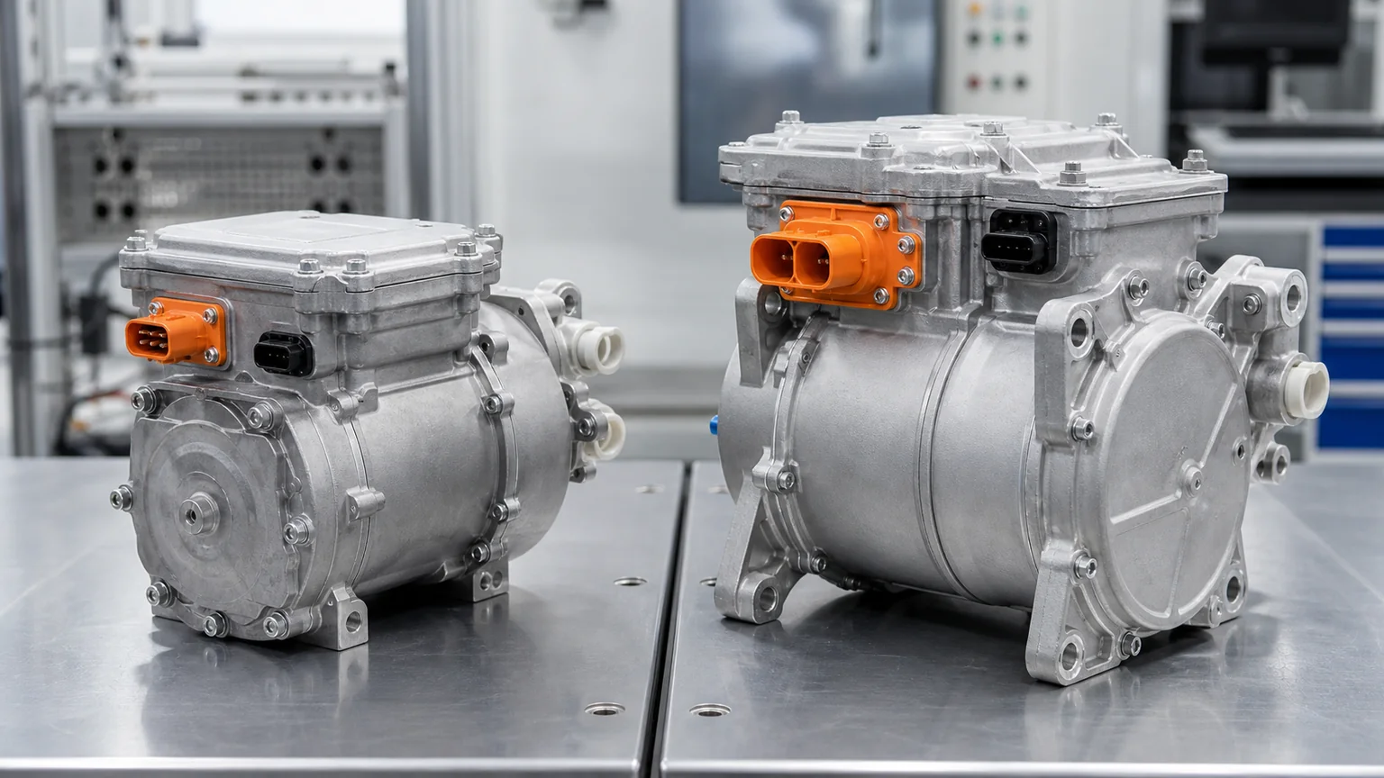
Compare the complete label, high- and low-voltage connectors, refrigerant ports, mounting, controller layout and allowed voltage range—not housing size alone.
Eight matching layers
1. Exact OE identity and revision
Record the vehicle VIN, production date, model, battery architecture, thermal-system option and original compressor label. Capture every number, QR or data-matrix code and hardware or software suffix. A platform can change compressor supplier, refrigerant, connector or controller during production without a visible change to the vehicle model name.
OE supersession evidence should state whether a later unit replaces the earlier hardware directly or requires a harness, bracket, hose, software update or calibration. Do not remove suffixes because the base number matches. For remanufactured units, traceability must link the housing and electronics revision to the supplied part number.
2. High-voltage operating window
Request minimum start voltage, continuous operating range, maximum input, permitted ripple or transient conditions and the controller’s undervoltage/overvoltage response. Nominal “400 V” or “800 V” should appear only beside that more precise data. The vehicle’s battery range and compressor range must overlap through the intended state-of-charge and temperature conditions.
Some architectures include a boost converter or another conditioned bus; others connect the compressor to the traction battery more directly. Confirm where the compressor receives power. Do not infer its input from the charge-port rating.
3. Inverter location and power interface
Most modern electric refrigerant compressors integrate a motor and inverter in one housing, but layouts vary. The high-voltage connector must match keying, terminal size, polarity, shielding, interlock and sealing. Orange color does not establish compatibility.
Record whether the high-voltage interlock loop passes through the connector and how the vehicle verifies closure. A connector that can be physically forced into place may damage the terminal, defeat the interlock or compromise water sealing. Never modify a high-voltage plug to fit.
Precharge and DC-link behavior also matter. An integrated inverter contains capacitors, and the vehicle may monitor inrush or discharge. The replacement controller must behave within the expected timing and diagnostic limits.
4. Low-voltage power and communication
The small connector can carry 12 V or another low-voltage supply, ground, wake, CAN, LIN, enable, speed command, interlock or diagnostic lines. Pin count and connector shell are not a pinout. Obtain the exact circuit and protocol for the part.
A compressor can have correct high voltage and still remain inactive because it receives no wake signal, expects another CAN identifier, uses different message scaling or rejects the vehicle’s authentication. Software compatibility belongs in the parts decision, not in a post-installation troubleshooting assumption.
5. Compressor capacity and operating envelope
Displacement, commonly stated in cubic centimeters per revolution, influences refrigerant flow but does not alone define capacity. Maximum and minimum speed, volumetric efficiency, pressure ratio, inlet condition, refrigerant, motor power and control limits also matter. Two compressors with the same displacement may have different performance maps.
Match the cooling and heating loads. Cabin-only cooling, battery fast-charge conditioning, reversible heat-pump heating, commercial-vehicle duty and rear HVAC can demand different operating envelopes. Oversizing can cause control instability or electrical overload; undersizing can produce sustained maximum-speed operation and inadequate thermal control.
6. Refrigerant, oil and electrical insulation
Confirm refrigerant and the compressor-approved lubricant by specification, not general family. R1234yf, R134a, R744 and R290 systems use different pressure, material and safety designs. No compressor should be converted between them based on similar ports.
In many electric compressors, refrigerant and oil contact the motor windings. The lubricant must preserve electrical insulation as well as lubricate. Mixing an unapproved oil, dye, flushing residue or excessive moisture can reduce dielectric performance and contribute to isolation faults.
7. Refrigerant ports and thermal integration
Compare suction and discharge port position, diameter, sealing seat, bolt or manifold pattern and orientation. Reverse connection can destroy the compressor. A hose manifold that appears to align may still have different passages or sealing geometry.
Heat-pump vehicles add routing complexity. Multi-way valves can reverse or redirect refrigerant, and the compressor may support cabin heating, battery cooling and waste-heat recovery. The controller and compressor map must be approved for those modes.
8. Mounting, vibration and package envelope
Record mounting-hole pattern, bushing design, installed angle, mass, ground or bonding features, connector access and clearance to the body, battery, undertray and coolant lines. Rubber isolators control vibration and should not be replaced with solid spacers. A compressor installed at an unapproved angle can affect oil management.
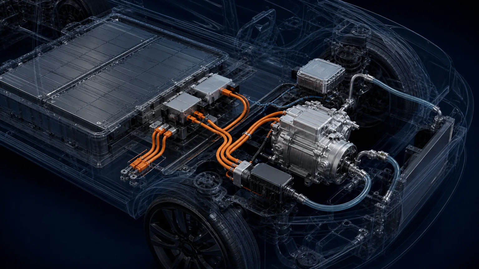
High-voltage DC powers the inverter and motor; a separate low-voltage connector carries supply, wake, interlock and CAN or LIN control according to the platform.
400 V versus 800 V comparison
Matching field
400 V-class compressor
800 V-class compressor
Buyer evidence
Nominal platform
Lower traction-voltage class
Higher traction-voltage class
VIN/OE architecture, not charge-port marketing
Allowed DC range
Part-specific minimum and maximum
Part-specific minimum and maximum
Supplier electrical specification
Current for equal power
Generally higher
Generally lower
Performance map at stated voltage and condition
Insulation/components
Validated for its own voltage/transients
Validated for higher voltage stress
Isolation, dielectric and qualification data
Capacity
Multiple displacements and speeds
Multiple displacements and speeds
Cooling/heating map; displacement is not enough
Connector/control
Platform-specific
Platform-specific
Connector drawings, pinout, protocol and software revision
Interchangeability
Not established by voltage class, housing or port position
Exact OE cross-reference or validated engineering approval
Connector inspection without unsafe probing
Photograph the connector faces after the vehicle has been made safe under the approved procedure. Record shell color and markings, key positions, terminal count, terminal size, seal condition, latch and high-voltage interlock features. Do not insert meter probes that spread female terminals or pierce sealed wiring.
Look for heat discoloration, tracking, moisture, corrosion, bent terminals, damaged shields and incomplete locks. A connector fault can generate isolation or communication codes that imitate a compressor failure. Replace terminals and housings only with approved repair parts and tooling.
Low-voltage communication should be diagnosed using circuit information, a scan tool and suitable test equipment. A standard multimeter may confirm supply and ground but cannot validate CAN message content. Oscilloscope work on network lines requires correct probing and interpretation; never connect a grounded bench instrument where it can bridge the high-voltage system.
Oil contamination and insulation resistance
An isolation fault after compressor work should trigger a system-level investigation. Moisture, mixed oil, contaminated refrigerant-service equipment, damaged windings, cable insulation, a heater or another high-voltage component can all affect the measured vehicle isolation. Do not condemn the compressor solely because the fault appeared after an A/C service.
Use the vehicle maker’s isolation procedure and approved insulation tester. Some electronic assemblies can be damaged by an inappropriate test voltage or polarity. Components may need to be isolated in a specified order, and stored energy must be discharged before connections change.
Document oil specification and quantity, refrigerant-machine history, recovered material appearance, moisture control and any dye. Do not flush an electric compressor unless its maker explicitly approves the method. Replace required driers, accumulators, expansion devices or contaminated heat exchangers according to the failure procedure.
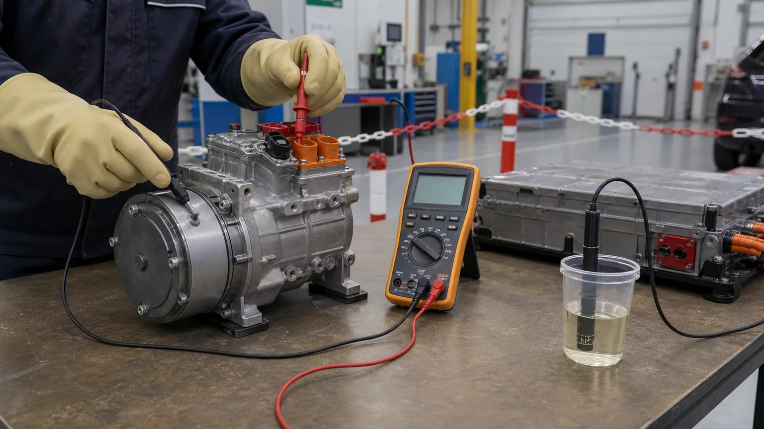
Verify the exact label and oil specification, control moisture and contamination, and perform isolation testing only with the platform-approved method and test voltage.
Performance matching beyond displacement
A compressor map relates speed, suction condition, discharge condition, refrigerant flow, power input and efficiency. Request performance at representative cabin cooling, battery chiller and heat-pump heating points. A single “maximum cooling capacity” number without conditions cannot be compared.
Battery fast charging may demand high cooling while the vehicle is stationary and ambient airflow is limited. The condenser fan, chiller, coolant pumps and compressor must work as a system. A higher-capacity compressor cannot compensate indefinitely for restricted heat rejection.
Low-temperature heating can require high pressure ratio and careful discharge-temperature control. The compressor controller may limit speed to protect the motor or oil. Match the intended refrigerant circuit, injection or economizer features if present, and operating limits.
Noise and vibration also matter. Electric operation makes tonal noise more noticeable than in an engine-driven vehicle. Mounts, speed-control strategy and refrigerant pulsation are designed together. A mechanically compatible alternative can create unacceptable resonance.
Electrical input is not cooling capacity
Do not label a compressor by multiplying one observed bus voltage by one current value. Electrical input changes with speed, pressure ratio, motor efficiency, inverter losses and controller limits. Cooling or heating output additionally depends on refrigerant mass flow and enthalpy change across the heat exchanger. A 5 kW electrical reading does not mean 5 kW of cooling, and a catalog cooling-capacity value cannot be treated as the compressor’s continuous electrical demand.
Request electrical input and refrigerant capacity at the same defined test point. The data should state suction pressure or temperature, superheat, discharge or condensing condition, subcooling where relevant, refrigerant, compressor speed and bus voltage. For a heat pump, request both cooling and heating operating maps and the discharge-temperature boundary.
Cable, contactor and fuse decisions remain vehicle-engineering responsibilities. Replacing a compressor with a unit that draws less current at one condition does not prove compatibility with inrush, peak load, fault current or protective coordination. Do not change high-voltage protection ratings to stop a repeated trip; diagnose the electrical and refrigerant load that caused it.
Failure patterns after an incorrect substitution
Observation
Possible mismatch
Evidence to collect
No start, no communication
Protocol, wake, pinout, low-voltage supply or software mismatch
Wrong oil, moisture, damaged windings/cable or another HV component
Service-fluid record and approved isolation sequence
Cooling weak at high load
Capacity/map mismatch, speed limit or system heat-rejection fault
Commands, speed, pressures, temperatures, fan/pump data
Abnormal noise or vibration
Mount, compressor map, port pulsation, refrigerant or oil mismatch
Mount photos, sound by speed, refrigerant data
Connector heating
Terminal, current or interface mismatch
Terminal inspection, voltage drop and thermal evidence
Bench testing has strict limits
Do not apply traction-battery voltage to an unidentified compressor. A safe functional fixture requires isolated high-voltage supply, precharge, current limiting, interlock, emergency stop, communication controller, refrigerant loop, oil and thermal loads. Spinning the compressor dry can damage it.
Low-voltage pin testing is also unsafe without a pinout. Applying 12 V to CAN, LIN or sensor lines can destroy the controller. Resistance readings across inverter terminals are difficult to interpret because semiconductor and capacitor circuits affect the meter.
Incoming inspection should prioritize non-energized evidence: label, revision, connectors, ports, caps, mounting, shipping damage, cleanliness and packaging. Functional or end-of-line data should come from the manufacturer or a qualified test facility with the correct part-specific fixture.
Remanufactured compressor controls
Remanufacturing a high-voltage compressor includes more than seals and bearings. The inverter, motor insulation, high-voltage connector, interlock, sensors and software identity need controlled evaluation. Replacement electronics must retain compatibility with the vehicle network and diagnostic expectations.
Request traceability for the original core number, supplied number, hardware and software revision, refrigerant/oil preparation, leak test, electrical isolation test and functional conditions. A freshly painted housing is not evidence of a validated controller.
Packaging must keep the compressor dry, capped and protected from connector impact. Hygroscopic oil and internal surfaces should not be exposed during warehouse inspection. Define maximum storage time and rotation if the supplier requires it.
RFQ fields for high-voltage compressor matching
VIN, make, model, production date, market and thermal-system option.
Complete old-compressor OE label, suffix, QR/data code and photographs.
Nominal platform voltage and permitted compressor DC input range.
High-voltage connector face, interlock and cable interface.
Low-voltage connector, pinout, supply, wake and CAN/LIN protocol.
Hardware/software revision and any required vehicle programming.
Refrigerant, oil specification, prefill state and charge handling.
Displacement, operating speed and performance map at required conditions.
Suction/discharge port geometry, sealing and flow orientation.
Mounting pattern, isolators, installed angle, envelope and mass.
Cabin, battery, charging and heat-pump duty requirements.
Order quantity, destination, packaging, labeling and traceability needs.
For fleet validation, log commanded and actual speed, bus voltage, current, pressures, refrigerant and coolant temperatures, ambient condition, charging state and diagnostic derating over representative routes. Tie every dataset to the exact compressor, vehicle software and thermal-control revision.
Exact OE number, vehicle configuration and revision are verified.
Allowed DC range covers the vehicle bus in all intended states.
Inverter, high-voltage connector, polarity and interlock match.
Low-voltage supply, pinout, network protocol and software match.
Refrigerant, oil, moisture control and insulation requirements match.
Displacement, speed and performance maps cover cabin and battery loads.
Ports, seals, mounting, isolators and installed angle match.
Service information specifies safe isolation, evacuation, charge and commissioning.
Traceability connects the supplied hardware and software revision to test evidence.
No adapter, repinning or software workaround is assumed without engineering approval.
Key conclusion: 400 V and 800 V identify broad traction-voltage classes, not interchangeable compressor families. Safe parts matching requires the complete electrical window, inverter and communication architecture, refrigerant/oil system, capacity map and physical interface. If any high-voltage or control field remains unresolved, keep the unit isolated and obtain an exact OE cross-reference or platform-specific approval.