You are here:Home » Blog » Technical Guides » AC Compressor Run-In After Installation: Oil Distribution, First Start, and Warranty Protection
AC Compressor Run-In After Installation: Oil Distribution, First Start, and Warranty Protection
Views: 0 Author: Elecdura Publish Time: 2026-09-01 Origin: Site
A replacement automotive A/C compressor should not be sent straight into maximum cooling demand. The safe commissioning path is to confirm the correct compressor, oil and refrigerant preparation, rotate the unit as required by its maker, start the system under controlled conditions, and watch pressures, sound and temperature while oil is distributed through the circuit. Exact speed, duration and control commands remain application-specific. If the supplied instructions or vehicle service data differ from a generic sequence, follow the product and vehicle data.
For workshops, distributors and warranty teams, run-in is not a ceremonial final step. It is the first controlled operating test after the refrigerant circuit has been opened. A disciplined first start helps distinguish a correct repair from a system-level problem before the new wholesale A/C compressor is exposed to avoidable load. It also produces evidence that is far more useful than a claim form containing only “compressor noisy” or “not cooling.”
Immediate stop conditions: stop the compressor when there is severe metallic noise, rapidly abnormal high-side pressure, no plausible pressure differential, visible refrigerant or oil leakage, smoke, a burning smell, an electrical isolation warning, or a hose and fitting condition that appears unsafe. Do not continue running in the hope that a serious symptom will disappear.
What run-in is designed to achieve
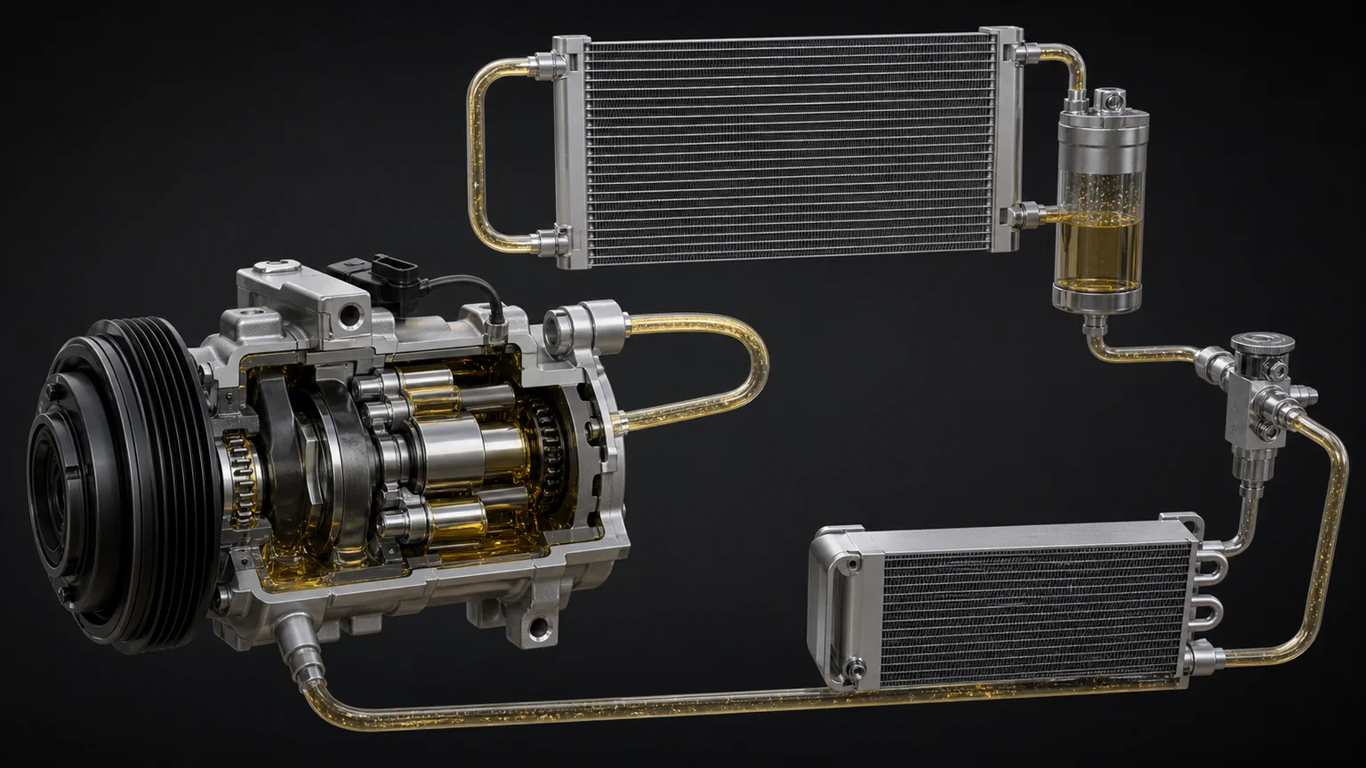
Compressor oil does not remain in one place. Some oil is held in the compressor, while some travels with the refrigerant and returns through the circuit. After component replacement, flushing, hose work or prolonged storage, the initial oil distribution may not resemble the stable distribution of a healthy operating system. Controlled operation gives the refrigerant/oil mixture time to circulate without immediately demanding maximum displacement, maximum condensing pressure or high engine speed.
The objective is not to “wear in” a badly matched compressor or cure contamination. Run-in cannot correct the wrong refrigerant oil, excessive oil, insufficient oil, residual flushing solvent, a blocked expansion device, a restricted condenser, a failed fan, a slipping drive, incorrect compressor control, or debris left from the previous failure. Those conditions must be addressed before the start command.
DENSO’s aftermarket guidance emphasizes the importance of correct compressor oil and explains that oil is vital to lubrication and heat removal. That principle is useful across compressor families, but the exact oil grade and total circuit quantity must come from the application data. Oil that is compatible with one refrigerant and compressor design may be unsuitable for another. Even oils sold under a similar family name can have different viscosity or additive requirements.
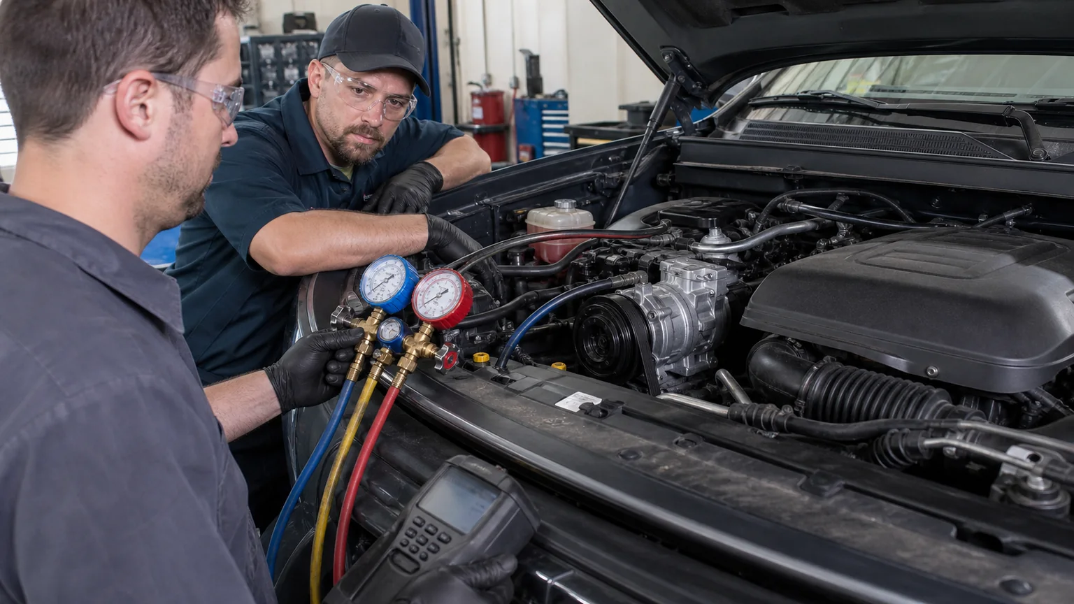
A controlled first start observes low-side pressure, high-side pressure, engine or compressor speed, discharge-line temperature, fan operation and abnormal sound together.
Separate belt-driven and high-voltage electric compressors
A belt-driven compressor is mechanically coupled to the engine through a clutch or a variable-displacement drive arrangement. Its start-up conditions are influenced by engine speed, belt condition, clutch engagement, control-valve command, condenser airflow and system pressure. The technician can often hold the engine at the speed stated in service guidance and can observe the clutch, belt and pulley directly.
A high-voltage electric compressor has no belt and may be commanded by the vehicle’s thermal-management controller. It can start because the battery, cabin or power electronics needs cooling, not only because the dashboard A/C button is on. Its oil must usually meet electrical-insulation requirements as well as lubrication requirements. Introducing an unapproved oil, dye, flushing agent or moisture can reduce dielectric performance. High-voltage work also adds isolation, personal-protective-equipment and scan-tool requirements.
Never transfer a belt-driven start-up routine to an electric compressor by analogy. Use trained personnel and the vehicle maker’s safe working procedure. The matching process for an electric A/C compressor must include the part number, voltage range, connector, communication/control type, refrigerant, oil, mounting and thermal-system architecture. A connector that physically fits is not proof of electrical or software compatibility.
Pre-start gate: do not energize the compressor until these checks pass
1. Confirm the replacement identity and application
Record the old and new labels before installation. Compare the complete part number, suffix, pulley diameter and groove count where applicable, mounting ears, rear-head port orientation, connector keying, control valve, clutch voltage, shipping plugs and included oil statement. For electric units, record rated voltage, communication details and any inverter or controller information available. Photographing both labels and the installed port orientation prevents later uncertainty.
Do not rely on vehicle model and year alone. Engine, market, production date, refrigerant option, rear A/C, hybrid powertrain and body configuration can change the compressor. A distributor’s automotive A/C compressor cross-reference should be treated as a selection aid and confirmed against the OE number and vehicle data.
2. Determine why the previous compressor failed
If the previous unit seized, produced metal debris or suffered severe internal wear, replacing only the compressor can place the new unit into a contaminated circuit. Inspect recovered oil and removed components. Follow the repair procedure for the condenser type, receiver-drier or accumulator, expansion device, hoses and flushable components. Modern parallel-flow condensers may trap debris and may require replacement rather than relying on a flush that cannot be verified.
A compressor that failed from high discharge pressure directs attention toward condenser airflow, fan operation, overcharge, non-condensable gas, a restriction or excessive heat load. A low-lubrication failure directs attention toward oil quantity, leakage, refrigerant charge and return conditions. An electrical control fault or belt drive problem must also be corrected. Run-in validates a repair; it is not a substitute for root-cause diagnosis.
3. Verify oil by type, amount and distribution
Read the compressor supplier’s oil statement carefully. “Contains oil” does not automatically mean “contains the complete vehicle-system charge.” It may mean the compressor contains a shipping amount, a full nominal amount, or an amount appropriate only for certain applications. Conversely, draining a prefilled compressor without following instructions can remove the intended charge or expose the unit to contamination.
Calculate oil replacement according to vehicle and compressor guidance, considering which components were replaced and how much oil was recovered. Use a clean, closed container and tools reserved for that oil. Hygroscopic oils absorb moisture from air, so containers should not remain open. Do not mix oils because their labels look similar. Record the brand, specification, batch if available, and measured quantity added or removed.
4. Check mechanical preparation
Confirm that shipping caps were removed only immediately before connection, O-rings are the correct material and size, sealing faces are clean, and fittings are torqued by the approved method. Check hose routing for twist, rubbing and contact with hot or moving parts. Inspect the belt, tensioner, idlers, crankshaft damper and clutch air gap where applicable. A contaminated or misaligned belt can create noise that is mistakenly blamed on the compressor.
If the compressor maker instructs manual shaft rotation, use the specified method and number of turns. Rotate the drive hub, not merely a free-spinning pulley that leaves the compressor shaft stationary. Resistance should be evaluated against the design; some variable-displacement units do not feel like a simple fixed pump. Do not force a unit that locks abruptly.
5. Evacuate and charge with measured equipment
Pressure testing, evacuation and charging are separate controls. Leak testing must use approved procedures and gases. Evacuation helps remove air and moisture, but a vacuum-hold result alone does not prove that every joint will remain leak-free under positive pressure. Charge refrigerant by the specified mass with calibrated equipment. Guessing from pressure alone is particularly unreliable when ambient temperature, fan operation and heat load vary.
Record the recovered refrigerant quantity, vacuum level and hold period, charged mass, ambient temperature and equipment identification. Confirm that service valves are closed and caps are installed after the test. If the system uses refrigerant concentration or leak-detection checks, complete them before returning the vehicle.
Oil is carried with refrigerant through the discharge side, heat exchangers, metering device and suction return; stable return depends on correct charge, flow and circuit condition.
A controlled first-start sequence
Prepare the observation area. Remove loose tools, route gauge hoses safely, close protective covers as required, and keep people clear of belts, fans and high-voltage components. Position a thermometer or temperature probes without creating an entanglement risk.
Record the baseline. Note ambient temperature, static system pressure after stabilization, battery voltage or vehicle state, engine-off belt condition, and any diagnostic trouble codes. Static pressure is not a refrigerant charge measurement, but an implausible value may reveal an obvious problem.
Establish condenser airflow. Verify that the radiator/condenser fan can operate when commanded and that the condenser is not blocked. Workshop airflow should be adequate. Water sprayed on a condenser can disguise an airflow problem and should not be used to make readings appear normal.
Start at the maker’s low-load condition. For a conventional vehicle, this commonly means engine idle, windows or doors open as instructed, blower operating and A/C enabled without racing the engine. However, use the exact vehicle or compressor procedure when it specifies another condition.
Observe engagement and pressure development. Watch whether the clutch engages cleanly or whether the control system commands displacement. Low and high pressures should begin responding in a plausible direction. Do not chase a target pressure before the system has stabilized.
Listen and inspect continuously. A brief change in sound at engagement can be normal; persistent grinding, hammering, severe squeal or rapidly increasing vibration is not. Check fittings and hoses for leakage, movement and abnormal heating.
Maintain the specified run-in speed and time. Some suppliers publish a defined engine speed and duration for oil distribution. Use those values when applicable. Do not substitute a higher speed to shorten the process.
Progress load gradually. After the controlled period passes, move through blower and temperature commands and, where instructed, a modest speed increase. Confirm fan stages and compressor modulation rather than jumping directly to maximum load.
Allow stabilization before judging performance. Evaluate vent temperature together with ambient conditions, humidity, air inlet mode, blower setting, refrigerant pressures and line temperatures. A single vent reading cannot describe the whole circuit.
Complete a post-run inspection. Switch off safely, allow pressures and temperatures to change as expected, inspect for oil traces or dye, reinstall caps and covers, and scan for new faults. Document the results.
The sequence intentionally avoids universal pressure numbers. Normal pressure depends on refrigerant, ambient temperature, cabin heat load, compressor control, fan airflow and system architecture. A fixed “low side must equal X” rule can condemn a healthy variable-displacement system or approve a faulty one. Use the manufacturer’s performance table or diagnostic procedure.
What to record during commissioning
Evidence
Why it matters
Minimum useful detail
Part identity
Proves the installed configuration
Old/new part numbers, labels, vehicle VIN/application, production date
System work
Shows contamination and moisture controls
Components replaced, flushing method, receiver-drier/accumulator and expansion-device action
Ambient, humidity if available, engine/compressor speed, blower, doors/windows, recirculation
Readings
Shows circuit response
Static and operating pressures, vent and line temperatures, fan command/operation
Sound and leakage
Separates immediate mechanical or sealing issues
Video or audio, leak-test result, close photos of fittings
Diagnostics
Captures control-system context
Pre- and post-run codes, relevant live data and command values
For a fleet or distributor, the most valuable record is a short standardized commissioning sheet attached to the job number. It should be quick enough that technicians actually complete it, while preventing the omissions that make a later investigation inconclusive. Passenger-vehicle programs can also group evidence by compressor family through a structured passenger vehicle A/C compressor catalog.
How to interpret common first-start observations
High-side pressure rises unusually fast
Stop before a protection device is forced to act. Check condenser fan command and rotation, airflow blockage, refrigerant mass, non-condensable gas, hose restrictions and valve position. Confirm that protective packing has not obstructed the condenser. A high-pressure event is a system symptom; replacing the compressor again will not restore airflow.
Little or no pressure differential develops
Confirm that the compressor is truly driven or electrically commanded, the clutch hub turns, the control valve receives the correct command, service couplers are open, and the gauge set is functioning. Check for gross refrigerant loss or internal bypass. On a variable system, use scan data and the maker’s diagnostic path before concluding that the new unit has no displacement.
Noise appears only when the A/C is enabled
Locate the sound rather than naming the compressor by proximity. Belt tensioners, idlers, the alternator, a loose bracket, hoses touching the body and a fan contacting the shroud can change sound under load. Compare clutch-on and clutch-off behavior, use safe acoustic tools, and inspect the drive. If metallic debris was present in the old circuit, stop and reconsider contamination control.
Cooling is weak but pressures appear plausible
Check air-mix doors, heater-valve behavior, cabin-filter restriction, blower airflow, recirculation operation and sensor plausibility. Measure inlet-to-outlet air temperatures under a defined condition. A refrigerant circuit can be working while heated air is mixed downstream, and a strong pressure snapshot does not prove correct cabin airflow.
The compressor cycles or derates quickly
Review pressure, evaporator-temperature, ambient-temperature and current signals. Modern controllers may reduce displacement or speed to protect the system or meet energy targets. Electric vehicles may prioritize battery conditions. Capture the command and feedback data; do not assume every speed change is a compressor defect.
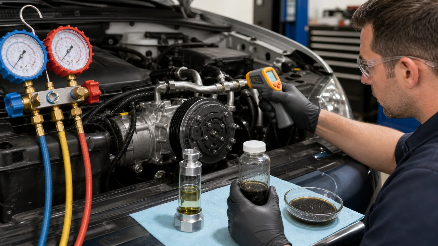
Evidence should connect each warning sign to pressure behavior, temperature, sound, control command, airflow and visible installation details.
Warranty protection comes from traceability, not prolonged operation
When a new compressor behaves abnormally, continuing to operate it can turn an identifiable system fault into extensive damage. The better warranty response is to stop, preserve recovered oil or debris when safe, photograph the labels and installation, save scan data, and contact the supplier with a concise evidence package. Do not dismantle a sealed compressor unless the warranty process authorizes it.
A useful claim states the timeline: original symptom, confirmed cause, parts replaced, cleaning or flushing action, oil and refrigerant records, evacuation and charge data, first-start conditions, readings, abnormal observation and stop point. It also identifies the tools used and whether they were calibrated. This allows a technical team to evaluate fitment, lubrication, contamination, airflow and controls instead of guessing.
Workshop commissioning checklist
Old and new compressor numbers, suffixes and physical interfaces match the verified application.
The previous failure cause was identified and all required circuit components were addressed.
Oil type, quantity and compressor prefill condition were confirmed and recorded.
Correct O-rings, clean sealing faces, approved torque and safe hose routing were used.
The shaft was rotated manually only when and as instructed.
Leak testing, evacuation and refrigerant charging were completed with measured equipment.
Condenser airflow, fan operation, belt drive and electrical supply passed inspection.
Baseline pressures, ambient conditions and diagnostic codes were recorded.
The first start used the specified low-load speed and duration.
Pressure response, temperatures, sound, leakage and control data remained plausible.
Load was increased gradually and final performance was assessed under documented conditions.
Post-run leakage, caps, covers, codes and job records were completed.
Information to send with a compressor inquiry
For faster matching and technical support, provide the OE compressor number, complete vehicle and engine data, refrigerant type, old-unit photos, connector and port views, pulley details or electric-compressor voltage information, and order quantity. If the request follows a failure, add the oil/refrigerant used, other components replaced, contamination evidence, initial pressure and temperature readings, diagnostic codes and a short sound video. Clear data protects the buyer, installer and supplier by making the decision reproducible.
Key conclusion: a careful A/C compressor run-in is a controlled commissioning test built on correct preparation. It distributes oil under manageable load, verifies that the entire circuit responds plausibly, and creates the evidence needed for reliable handover or warranty review. It cannot rescue an incorrect part, contaminated circuit, wrong oil, inaccurate charge or failed airflow system.