You are here:Home » Blog » Technical Guides » Blower Motor Regulator Heat-Sink Installation: Thermal Grease, Airflow, and Repeat Failure
Blower Motor Regulator Heat-Sink Installation: Thermal Grease, Airflow, and Repeat Failure
Views: 0 Author: Elecdura Publish Time: 2026-09-01 Origin: Site
A replacement blower motor regulator can fail again if the heat sink is not seated as designed, airflow across it is restricted, the connector has resistive heat damage, or the blower motor draws excessive current. Correct installation therefore combines part identification, clean mechanical seating, only the specified thermal interface material, secure airflow exposure, circuit voltage-drop checks and a current test across several blower commands. Replacing the module alone is not a complete diagnosis.
Electronic blower regulators—also called final-stage units, power modules or blower control modules—control current to the cabin blower motor. Their finned heat sinks are often positioned inside the HVAC air stream because the power electronics produce heat. Buyers selecting a wholesale blower motor resistor or regulator must distinguish these modules from simple stepped wire-wound resistor packs. The mounting, connector, control signal and cooling method are not interchangeable.
Important boundary: use the vehicle and module maker’s instructions for thermal compound, pad, seal, fastener torque and electrical testing. Some designs require a specific interface material; others transfer heat through airflow and mechanical geometry without added paste. Excess or electrically conductive compound can create faults.
Why the heat sink is part of the electrical design
A blower motor requires substantial current, especially at high speed. In a traditional resistor pack, resistive elements drop voltage for lower speeds and release heat directly into the air stream. In an electronic regulator, semiconductor devices switch or modulate power more efficiently, but conduction and switching losses still become heat. The aluminum heat sink moves that heat away from sensitive junctions.
Cooling performance depends on the complete thermal path: semiconductor to internal substrate, substrate to module housing or heat sink, heat sink to moving air, and HVAC case to the surrounding environment. A poor interface, blocked fins or low airflow raises semiconductor temperature even if electrical current remains within the nominal range. Elevated temperature can shorten component life and may trigger protective shutdown or unstable blower behavior.
HELLA’s technical overview explains that electronic interior-blower regulators allow continuously variable control and are installed near the blower motor for cooling. That architecture shows why installation position matters. Moving a module outside its intended duct, leaving it partly withdrawn or using a cover that blocks airflow changes its operating conditions.
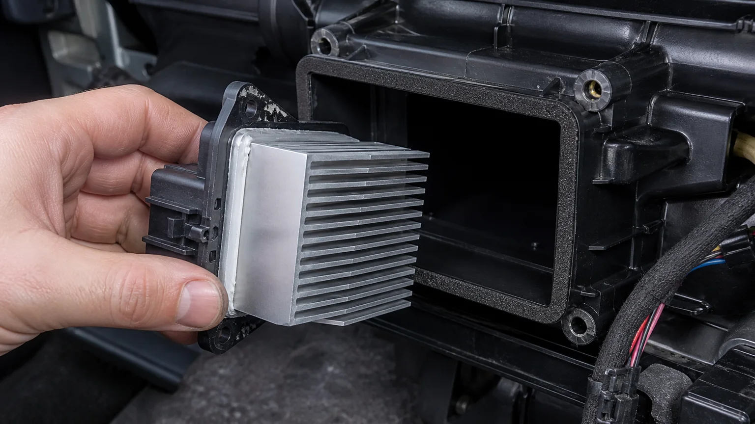
The regulator must seat in the intended HVAC opening with its heat sink exposed to airflow and its sealing or thermal interface installed exactly as specified.
First identify what type of speed-control device is installed
A stepped resistor pack normally supports several fixed blower speeds. It may contain coiled resistive elements and a thermal fuse, with high speed bypassing some or all resistance. A failed pack often removes one or more lower speeds while high speed remains. Its open elements are cooled in the duct.
An electronic regulator generally supports smooth or finely stepped speed commands. It contains power semiconductors and a finned metal heat sink. Depending on vehicle design, failure can cause no blower, full-speed operation, intermittent running, operation after key-off, or speed that does not follow the command. These symptoms overlap with motor, wiring, control-head and network faults.
Some commercial vehicles and older platforms use relays, multiple resistor assemblies or separate controllers. Do not classify a part only by the informal name on an invoice. Use the OE number, connector pinout, circuit diagram, physical construction and HVAC system option.
Diagnose the root cause before fitting the new module
Inspect the blower motor mechanically
With power isolated and access made safe, check the blower wheel for leaves, labels, insulation or broken pieces. Turn the wheel as permitted and feel for rough bearings, rubbing, tight spots or excessive play. A motor that drags mechanically can demand more current and send additional heat through the regulator and connector.
Inspect the wheel for cracks, missing balance weights or contamination. An imbalanced wheel can damage bearings and create current fluctuation. Water entry can corrode the motor, connector and module. Correct a blocked drain, leaking cowl or wet cabin filter rather than installing electronics into the same environment.
Inspect the air path
A severely restricted cabin filter reduces airflow through the HVAC case. Closed or obstructed ducts, a contaminated evaporator, a misinstalled filter, packaging left in the intake, or a recirculation door fault can also reduce cooling air. Replace or clean components according to service guidance and confirm that air can reach the heat sink in every relevant operating mode.
Do not use the absence of strong outlet air alone to condemn the blower motor. Door position, filter restriction and evaporator icing alter delivered flow. Measure motor current and voltage while noting the command and air-path condition.
Inspect connector and terminals
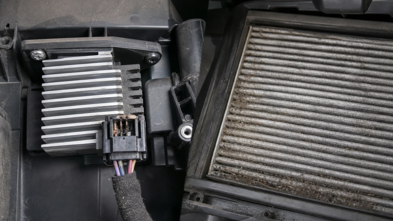
Disconnect with the approved procedure and look for browned plastic, melting, a displaced terminal, green corrosion, loss of spring tension, fretting or an overheated crimp. Heat can originate at a high-resistance terminal even when motor current is not excessive. Once a terminal loses tension, replacing only the regulator leaves the resistance in place.
Use the specified repair connector or terminal procedure. Twisting wires together, installing undersized generic terminals or soldering in a stiff section where the harness flexes can create another failure. Maintain wire gauge, insulation temperature rating, seal and strain relief. Record pin positions before de-pinning.
Check supply, ground and command
A circuit diagram should identify power feed, ground, motor output and control or communication lines. Test the correct circuit rather than applying battery voltage to unknown pins. On networked controllers, a scan tool may be needed to compare requested and actual blower operation.
Voltage measured with the circuit unloaded can appear normal despite a poor connection. A voltage-drop test under operating load is more revealing. Measure the power-side drop and ground-side drop according to service specifications. Keep meter leads and hands clear of the moving blower.
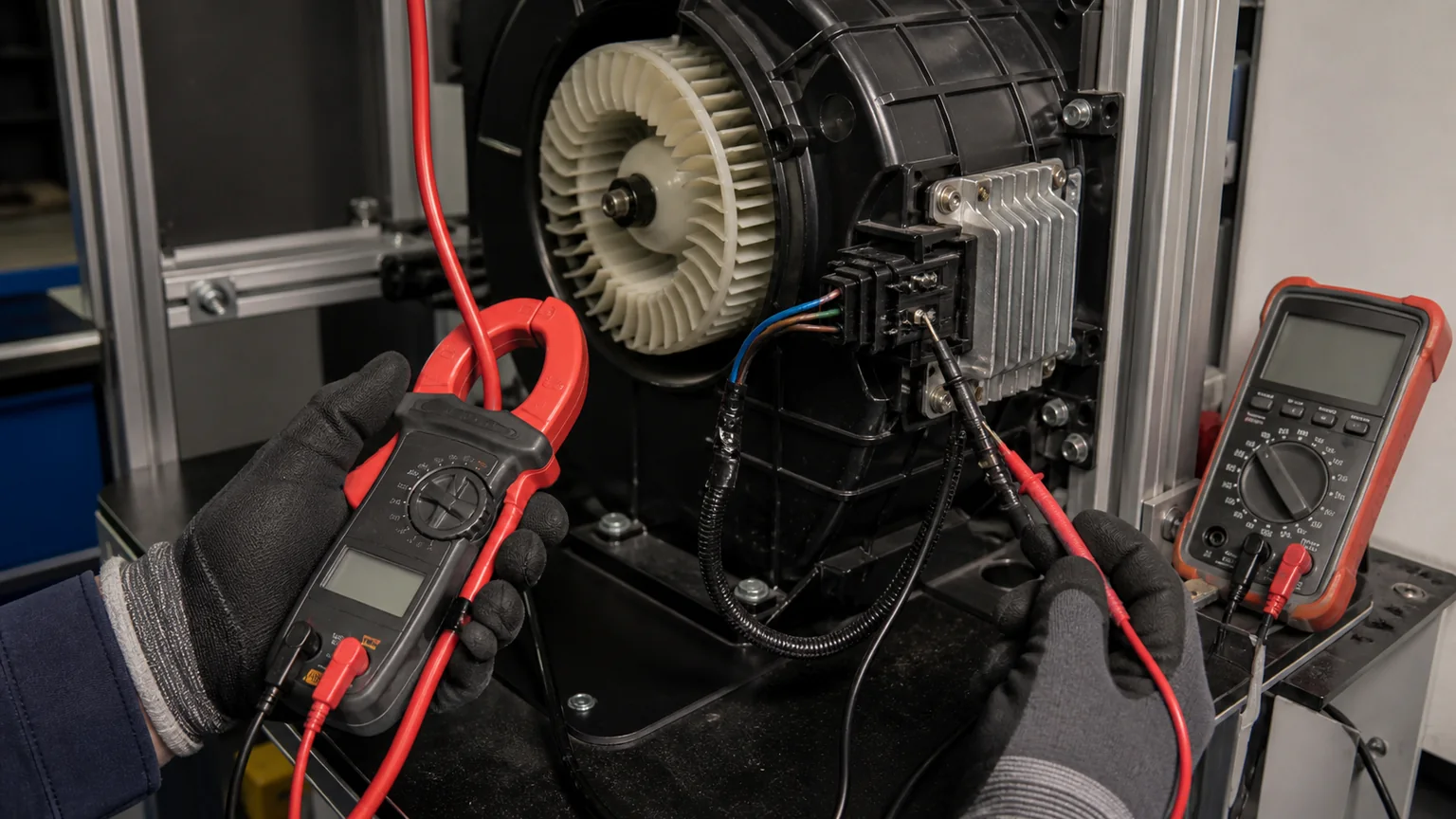
Record current, supply voltage, ground drop, command and blower behavior together at several speed requests rather than relying on an unloaded voltage check.
Measure blower current without creating a new fault
Use a suitably rated current clamp or the manufacturer-approved method. Confirm the instrument range, zero the clamp and orient it correctly. Do not place a small multimeter current input in series with a high-current blower circuit unless the procedure and meter rating explicitly allow it. An overloaded lead or fuse can be dangerous.
Test at several commanded speeds after the system is safely assembled. Record battery or charging voltage because motor current and speed change with supply. Compare readings with service data or a known-good equivalent under similar conditions. A universal current limit is inappropriate: motor size, vehicle voltage, airflow load and control strategy vary.
Look for patterns. Current that rises sharply as the motor warms can indicate bearing or winding trouble. Erratic current can accompany a worn commutator, intermittent terminal or rubbing wheel. Low current with poor airflow may point toward low supply voltage, excessive circuit resistance, a blocked wheel or a control command issue. High current should not be “solved” with a larger fuse.
If the regulator has already failed and cannot run the motor, test the motor only by an approved alternate method. Direct powering may bypass protection and can damage electronics if performed through the wrong terminals. When uncertainty remains, replace a suspect motor along with the regulator only when evidence or service guidance supports that decision.
Prepare the mounting opening and heat sink
Disconnect the battery or isolate the system as required, then wait for specified module discharge periods. Remove trim and ducts without forcing clips into the blower wheel. Vacuum loose debris before withdrawing the old module so contamination does not fall into the case.
Compare old and new units side by side. Check OE and supplier numbers, connector keying, pin count, heat-sink fin shape and depth, mounting flange, screw locations, seal or gasket, locating tabs and overall insertion length. Similar modules can use different control electronics even when their housings look alike.
Inspect the HVAC opening for distortion, melted plastic, debris and damaged screw bosses. The module must reach its locating surface without force. Bent fins may obstruct insertion or airflow. Do not grind the heat sink or cut the case to make a near-match part fit.
Thermal grease, pads and dry interfaces
Thermal interface material fills microscopic gaps between designed heat-transfer surfaces; it is not an adhesive or a substitute for mechanical seating. If the application specifies compound, use the stated type and quantity. Apply a thin, even layer to the stated area. Thick blobs can insulate, spread onto terminals or prevent full seating.
Some compounds are electrically insulating; others may conduct electricity or become mobile at temperature. Do not use household, computer or generic automotive grease merely because it transfers heat in another application. Silicone compatibility, pump-out, volatility, corrosion and dielectric properties matter.
If a preformed pad or gasket is supplied, do not automatically add paste on both sides. Pads have defined thickness and compression. Reusing a torn or permanently compressed pad can leave air gaps. A perimeter foam seal may control airflow rather than transfer heat; omitting it can let air bypass the heat sink.
Many regulators dissipate heat directly from their fins into duct air and do not have an external metal-to-metal mounting face that needs added compound. In that design, applying paste around the plastic flange offers no benefit and can contaminate the case. Product instructions decide the method.
Installation sequence
Verify the circuit is safe. Isolate power as specified and keep the blower from starting while hands are in the case.
Clean the opening. Remove debris without pushing it deeper into the evaporator or wheel. Dry any moisture and correct its source.
Prepare the interface. Install only the specified new seal, pad or measured thermal compound. Keep terminals and locating features clean.
Insert squarely. Align fins and locating tabs. The unit should seat on its designed flange without using screws to pull it through an obstruction.
Fasten correctly. Use the original or specified fasteners and tightening sequence. Avoid stripping plastic bosses or warping the flange.
Repair and connect the harness. Confirm terminal retention, connector lock, seal and strain relief. Route wiring away from the blower and sharp edges.
Restore the air path. Reinstall covers, ducts, filter and trim so the heat sink receives intended airflow.
Reconnect and test. Follow battery reconnection, initialization and diagnostic procedures. Command several blower speeds while measuring the planned values.
When the module is attached to a separate heat spreader or case surface, tighten evenly to maintain contact. Do not assume maximum hand force gives better heat transfer. Over-tightening can crack the module, strip the case or squeeze out the interface material.
Repeat failures often leave combined evidence: a heat-discolored terminal, damaged crimp, blocked filter, debris-loaded wheel or a module that was not fully seated in the duct.
Post-installation validation
Operate the blower from minimum through maximum command and back down. Confirm smooth response where the system is designed for variable speed. Check whether the blower stops with the key and command in the specified states. Observe for intermittent operation over a reasonable warm-up period.
Record supply voltage, power and ground voltage drops, motor current at defined commands, diagnostic trouble codes, control request and actual behavior. If a thermal camera is used, follow electrical safety and emissivity limitations. Surface temperature is useful for comparison but does not directly equal semiconductor junction temperature.
Check the connector again after operation. A newly warming terminal indicates unresolved resistance. Smell, discoloration or softening plastic is a stop condition. Do not leave the blower operating unattended to “burn in” a suspect repair.
Verify air volume and listen for wheel contact. Reinstall any acoustic insulation and splash protection because water and debris control affect long-term reliability. Clear codes only after saving the pre-repair record and confirming that no relevant fault returns.
Symptom-led decision table
Observation
Checks before blaming the new regulator
No blower at any speed
Fuse and feed, ground under load, motor continuity/condition, command signal, connector pinout, network faults
Blower runs only at maximum
Module type, bypass/relay circuit, lower-speed command, regulator ground and control line
Motor current trend, terminal resistance, heat-sink airflow, seating, thermal interface and module protection
New module fails quickly
Overcurrent motor, blocked wheel/filter, melted connector, wrong part/control type, water entry, incorrect interface material
Weak airflow with normal command
Supply drop, motor wear, filter/duct restriction, recirculation door, wheel condition and installation direction
Evidence for a repeat-failure review
Keep the failed regulator intact unless the supplier authorizes opening it. Photograph the label, fins, mounting face, seal, connector and surrounding case. Photograph the motor and cabin filter. Save the connector-repair details, current readings, voltage drops, trouble codes and operating conditions. State how long the earlier replacement operated and at which blower settings the symptom appeared.
A useful timeline distinguishes the original complaint, first diagnosis, parts fitted, remaining root cause and second failure. If a worn blower motor assembly overloaded the module, the investigation should show current or mechanical evidence. If the terminal heated, close photographs and voltage drop are more meaningful than a generic claim that the module “burned.”
Procurement checks for distributors
Catalog master data should distinguish resistor packs, regulators and complete controllers. Record OE cross-references, connector face and pin count, nominal system voltage, heat-sink envelope, mounting and seal arrangement, control type and compatible blower system. Use multiple product views rather than a single front image.
Incoming inspection can verify label, connector keying, terminal alignment, fin damage, flange flatness, seal presence and packaging protection. Electronic function testing requires an approved fixture and known load; applying uncontrolled voltage to a signal pin can destroy the part. Require lot traceability and define how revised electronics or housings will be communicated.
The OE number, electronic or resistor type, connector, heat sink and mounting match.
The blower wheel turns correctly and has no debris, rubbing or excessive play.
The cabin filter, intake, evaporator face and ducts do not restrict cooling airflow.
Water entry and blocked drains have been corrected.
Connector plastic, terminal tension, crimp and wiring pass inspection.
Supply and ground are tested under load, not only with the circuit open.
Motor current is recorded at defined commands and voltage.
The mounting opening is clean and undamaged.
Only the specified thermal compound, pad or seal is used in the correct amount.
The heat sink is fully inserted into its intended airflow and the module seats squarely.
Harness routing, connector lock, ducts, covers and filter are restored.
Blower response, current, voltage drop, codes and connector temperature pass final checks.
What to send with a parts or warranty inquiry
Provide the OE and supplier numbers, vehicle VIN/application and HVAC option, clear connector and heat-sink photos, pin count, old and new labels, and required quantity. For a technical case, add blower current at several commands, supply and ground voltage drops, diagnostic codes, filter and airflow condition, blower-wheel inspection, evidence of water entry, and close photographs of every overheated terminal.
Key conclusion: heat-sink installation is one part of a system repair. Correct seating and the specified thermal interface protect the regulator, while clean airflow, a healthy motor and low-resistance connections keep heat generation within design limits. Measuring the loaded circuit before and after replacement is the strongest defense against another failure.