A turbocharged engine can lose boost performance even when the charge-air cooler passes a basic leak test. Air must travel through hundreds of narrow internal passages, and crushed tubes, oil deposits, foreign material or an unsuitable replacement core can create resistance without producing an obvious external leak. The turbocharger then works across a larger pressure ratio to deliver the requested manifold pressure, increasing compressor outlet temperature and potentially reducing available air mass.
A charge-air cooler pressure drop test compares stabilized pressure at the cooler inlet and outlet under the same mass-flow condition. It should be read together with inlet temperature, outlet temperature, engine speed, load, ambient condition and boost command. Elecdura’s charge-air cooler assembly range includes different core geometries and connections, so neither a universal pressure-drop number nor an appearance-only match is reliable.
Quick answer: first prove that the charge-air circuit is sealed and that the pressure sensors are plausible. Install matched pressure channels as close as practical to the cooler inlet and outlet, record both at the same instant, and reproduce a controlled load point. Calculate inlet pressure minus outlet pressure while also recording temperatures and airflow-related data. A pressure loss that rises disproportionately with flow supports internal restriction; a low temperature reduction with modest pressure loss points toward poor heat rejection; unstable pressure accompanied by leakage evidence points toward a hose, joint, tank or core leak rather than simple restriction.
Pressure Drop, Leakage, and Cooling Efficiency Are Different Faults
These three conditions are often grouped under “bad intercooler,” but they describe different physics. Pressure drop is the resistance between inlet and outlet while air flows. Leakage is mass leaving the intended path. Thermal inefficiency is inadequate removal of heat from the compressed air. One cooler can suffer more than one condition, but each requires separate evidence.
Fault
Primary measurement
Typical supporting evidence
Common confusion
External leak
Pressure decay or flow leakage under a controlled test
Oil track, bubbles, smoke escape, loose joint
Turbo control fault
Internal restriction
Inlet-to-outlet pressure difference under load
Drop rises steeply with mass flow; damaged or fouled tubes
Intake restriction or exhaust backpressure
Poor heat rejection
Inlet/outlet temperature relationship at controlled load
Blocked external fins, recirculated hot air, inadequate vehicle airflow
Excess pressure drop
Sensor bias
Reference comparison and key-on plausibility
Offset remains without flow
Actual cooler restriction
Why a leak test cannot prove low restriction
A sealed cooler with partially collapsed tubes may hold static pressure perfectly. Static leak testing establishes containment, not flow capacity. Conversely, a cooler with a small leak may show little pressure difference between two sensors because both sides lose pressure together. Keep the test questions separate.
Pressure loss must be linked to mass flow
Every sound cooler produces some pressure loss. The diagnostic question is whether the loss is excessive for that exact application and operating point. Compare with manufacturer data, a verified reference vehicle or a controlled baseline—not with an arbitrary internet limit.
Understand Where the Measurements Belong
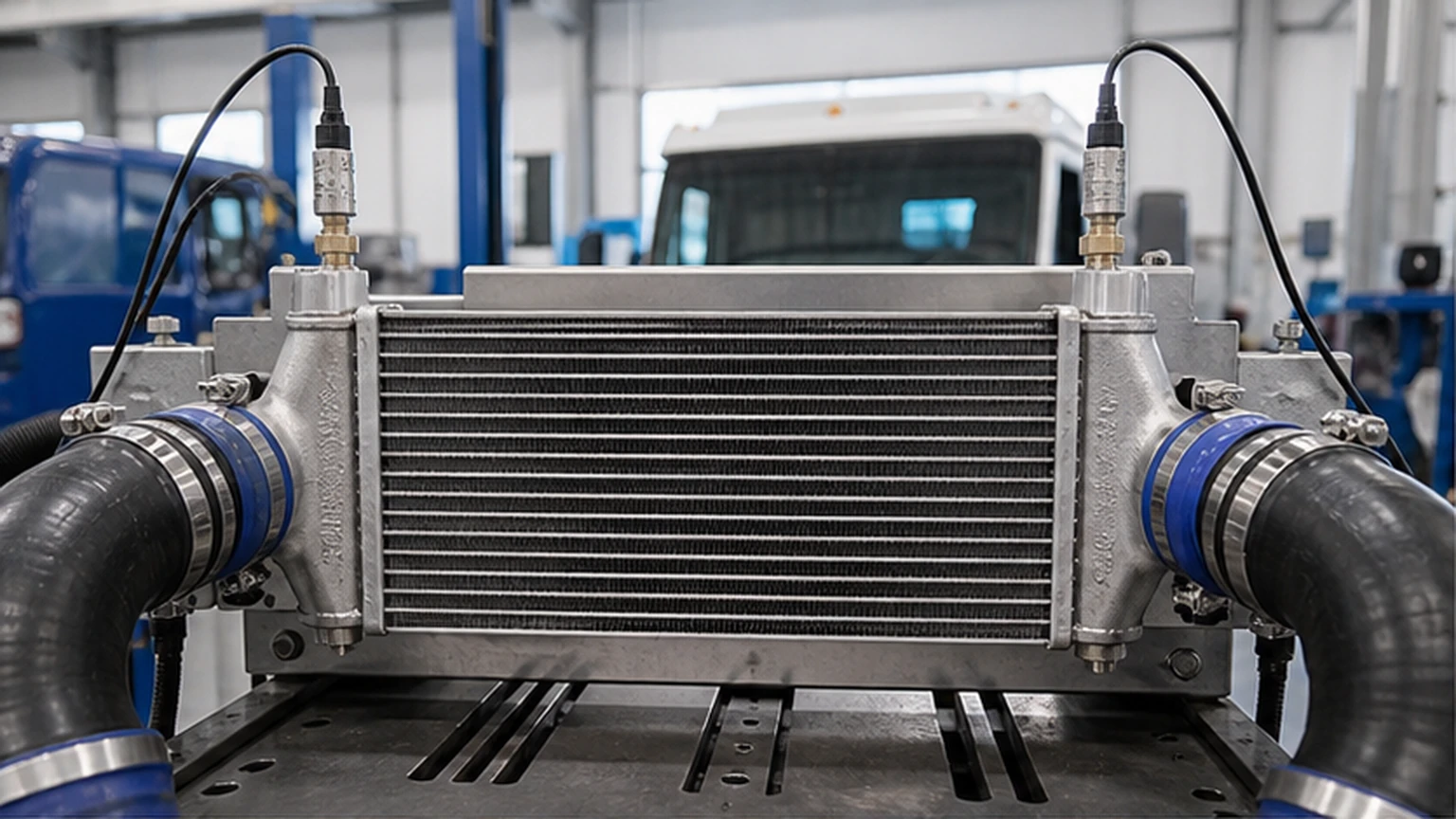
The inlet channel should represent pressure immediately before the cooler core, and the outlet channel should represent pressure immediately after it. Long hoses, elbows, resonators, throttle devices and test fittings add their own losses. If sensors are placed far from the core, the calculated result becomes a system pressure drop rather than a cooler-only measurement.
Use matched sensors and synchronized logging
Two channels should have suitable range, response and accuracy. Zero them together and compare their readings at equal static pressure before installation. Sequential readings from one gauge are weak evidence during a changing acceleration because engine flow may differ between samples.
Matched, synchronized pressure channels isolate the loss across the cooler at a controlled flow point.
Use safe, sealed test ports
Follow the service procedure for port location and fittings. A loose adapter becomes a new boost leak, while a protruding probe can disturb flow. Secure hoses away from fans, belts, exhaust heat and road contact, and use equipment rated for expected temperature and pressure.
Establish Sensor Plausibility Before the Road Test
With the engine off and the charge circuit at atmospheric pressure, the two added channels should agree within their stated tolerance. Compare relevant vehicle pressure sensors with barometric pressure where the service information permits. A fixed offset between channels will appear as false pressure drop at every load.
Check the rest of the boost-control evidence
Record requested boost, actual manifold pressure, turbo actuator command, mass airflow, engine speed and fueling. A turbocharger that never produces the requested inlet pressure cannot be used to condemn the cooler for downstream pressure. Likewise, an incorrect manifold sensor can make the control system overwork the turbo while the physical cooler remains normal.
Elecdura’s guide to intercooler leak symptoms covers containment faults; the present test begins after hoses, clamps and tanks have been checked well enough to support a restriction measurement.
Create a Repeatable Load Point
Pressure drop changes strongly with airflow, so “full throttle” is not a precise test condition. Use a chassis dynamometer, engine dynamometer or manufacturer-approved road procedure that can reproduce engine speed, gear, load and duration safely. Log a stable window rather than selecting an isolated spike during a shift or throttle transient.
Account for altitude and ambient temperature
Air density changes mass flow for a given pressure reading. Ambient temperature also changes heat rejection and compressor outlet temperature. Record both and compare only conditions that are sufficiently similar or normalized by the specified procedure.
Do not create unsafe stationary load
A workshop acceleration without appropriate load may not reproduce high mass flow, while an improvised brake-load test can overheat the drivetrain. Use approved equipment, adequate ventilation and trained personnel. For off-highway equipment, reproduce a controlled hydraulic or working load according to the machine procedure.
Calculate and Interpret the Pressure Difference
At each stable point, subtract outlet absolute pressure from inlet absolute pressure. If gauge-pressure sensors share the same atmospheric reference, their difference can also be useful, but record the units and method. Plot pressure difference against a flow-related variable such as mass airflow, corrected engine flow or comparable load point.
Restriction produces a flow-dependent pattern
As airflow increases, friction and local losses increase. A restricted core may look acceptable at idle yet produce a rapidly growing difference under load. Compare multiple points. A sudden step can reflect a collapsing hose, loose internal baffle or sensor range issue rather than uniform core fouling.
Do not diagnose from the peak alone
Transient compressor surge, throttle closure or gear change can create a short differential that does not represent steady flow. Use time-aligned graphs and select a stable operating window. Repeat the run to confirm that the curve is reproducible.
Add Temperature to Separate Restriction From Poor Cooling
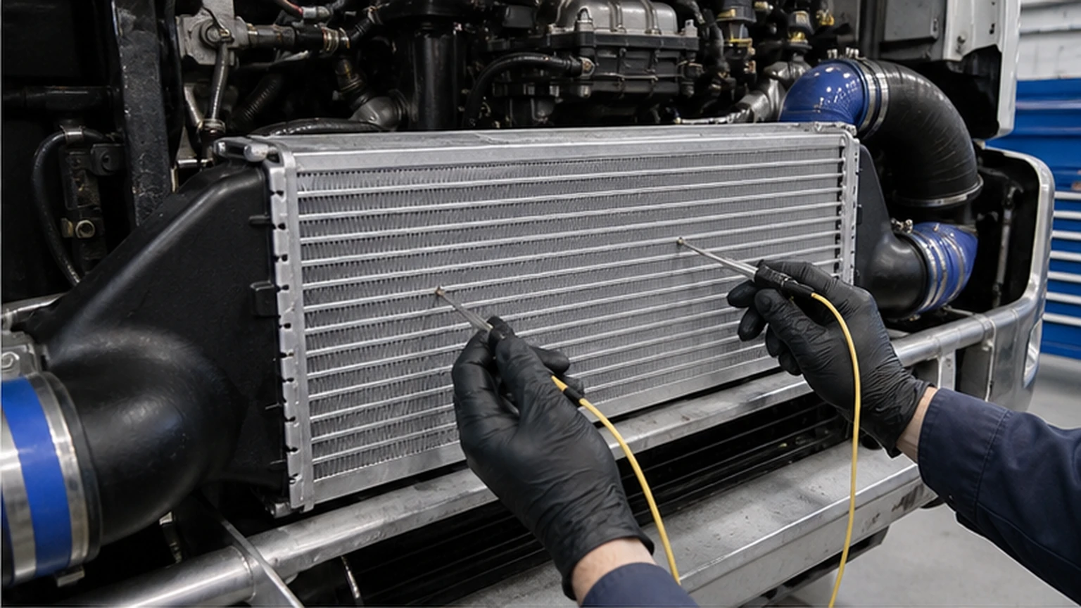
Measure charge-air temperature close to the same inlet and outlet boundaries. The cooler should reduce temperature when vehicle-side airflow and thermal conditions allow, but the expected change depends on load, ambient air, vehicle speed, fan operation, core area and heat soak.
Temperature channels show heat rejection, while pressure channels show flow resistance.
Low temperature reduction with modest pressure loss
This pattern points away from internal flow restriction. Inspect external fin blockage, missing seals, hot-air recirculation, fan operation and vehicle-side airflow. An externally dirty core may pass air internally with normal pressure loss while rejecting too little heat.
Large pressure loss with a strong temperature change
A restricted passage can increase residence time and still produce an apparently good outlet temperature at reduced mass flow. Cooling appearance does not cancel the pumping penalty. Engine performance depends on both air temperature and delivered mass.
Heat soak can reverse the first observation
After idling, a hot core may temporarily warm the charge air. Stabilize the test or interpret the transient explicitly. Do not compare a heat-soaked first run with a fully ventilated later run without noting the difference.
Inspect External and Internal Restriction Evidence
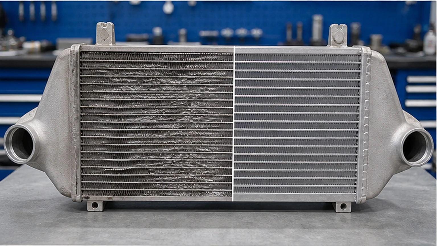
Inspect the entire external face, not only the visible center. Debris can pack between stacked heat exchangers. Bent fins, mud, insects, paint and corrosion reduce vehicle-side airflow. Look for crushed tubes, tank deformation and mounting stress caused by collision or incorrect installation.
Oil film is evidence, not an automatic failure verdict
A light oil film can occur in some turbocharged intake systems, while pooling or heavy deposits require investigation of the crankcase ventilation system, turbocharger and operating history. The article on oil found inside an intercooler explains that oil source diagnosis should precede cooler replacement.
Internal cleaning has limits
Use only an approved method and confirm that all cleaning fluid is removed. A solvent may attack seals, leave residue or create a combustion hazard. Cleaning cannot restore a crushed tube, separated internal fin or deformed header. If contamination came from a failed turbocharger, define how the entire charge path will be cleaned before a new part is fitted.
Never judge an internal passage only from the port
Visible inlet cleanliness does not show the depth of every tube. Borescope evidence, drained contamination, weight comparison and measured flow can support the decision, but the permitted inspection method depends on core design.
Rule Out Components That Can Mimic Cooler Restriction
An intake filter restriction reduces compressor inlet pressure. Exhaust backpressure reduces turbine energy and engine breathing. A delaminated hose can close under suction or deform under boost. Turbo actuator, wastegate or variable-geometry faults change pressure production. EGR and throttle strategies can alter fresh-air mass. Diagnose these branches before assigning every boost deficit to the cooler.
Competing fault
Why it looks similar
Separating evidence
Charge hose delamination
Flow loss rises with load
Hose deformation and localized pressure change outside cooler boundary
Turbo control fault
Low downstream boost
Inlet pressure to cooler never reaches expected value
Exhaust restriction
Poor power and high temperature
Backpressure and turbo-speed evidence
Pressure-sensor bias
Calculated differential appears high
Static cross-check shows channel offset
External airflow blockage
Hot outlet air and reduced power
Pressure loss remains modest while thermal performance is poor
Repair, Clean, or Replace?
Correct external airflow faults first
Restore missing seals, fan performance and safe fin cleanliness, then repeat the synchronized test. Elecdura’s cooling fan range and fan control modules belong in the order only when their own command, power and airflow evidence confirms a fault.
Replace a structurally damaged or persistently restricted core
Replacement is justified when crushed passages, separated joints, unrepairable tank damage or verified excessive pressure drop remains after permitted cleaning and system causes are addressed. A leak repair must follow an approved process and preserve pressure capability; cosmetic patching is not wholesale quality evidence.
Retest the complete circuit after replacement
Verify pressure drop, temperature response, boost control, hose security and absence of leaks under the original load condition. If a new cooler immediately accumulates oil or debris, the upstream failure has not been corrected.
Replacement Matching for Passenger, Truck, and Equipment Cores
Provide the OE number, vehicle or machine model, engine, model year, market, rated power and emission configuration. Photograph inlet and outlet orientation, hose connection type, mounting points, sensor ports and adjacent brackets. Record overall core height, width and thickness separately from tank dimensions.
Core geometry changes performance
Fin density, tube count, internal turbulators, core depth and tank distribution affect both heat transfer and pressure loss. A unit that fits the opening may not reproduce the original balance. Do not infer performance from outside dimensions alone, and do not transfer an acceptance limit from a passenger vehicle to a semi-truck or excavator.
Ask whether seals, clips, brackets, sensors, hoses and protective caps are included. A complete cooler may still require application-specific transfer parts. Record required quantity, packaging marks and inspection level for the quotation.
Wholesale Quality Control and Transport Protection
Receiving inspection should check core squareness, tank joints, thread and bead condition, mounting alignment, fin damage, cleanliness and protective caps. Sample leak tests must use an agreed pressure, medium, stabilization time and allowable decay or flow. A pressure test alone does not validate flow capacity, so supplier approval may also require a comparative pressure-drop fixture.
Prevent shipping damage from becoming test noise
Rigid corner protection and clearance around hose necks prevent carton loads from bending the assembly. Ports should be capped against moisture and foreign material. Avoid packaging that presses directly on delicate fins. Photograph pallet and carton condition when damage is found so the manufacturing and transport causes can be separated.
Use traceable samples
Link every pressure, flow and dimensional result to lot, part number and sample identity. For a new program, compare samples against a verified original and retain raw curves rather than a pass/fail statement only. The Elecdura wholesale program can coordinate a mixed cooling order, but each core still needs its own application evidence.
Keep adjacent heat exchangers outside the cooler verdict
A stacked cooling module may include a condenser, engine radiator and charge-air cooler sharing the same vehicle-side air stream. Inspect the radiator fan motor and any mechanical fan clutch when stationary airflow is inadequate, but do not use that finding as proof of internal charge-air restriction. Related engine cooling components should be quoted only when their own leakage, airflow or thermal evidence supports replacement. This boundary keeps a shared-airflow problem from inflating the cooler order.
FAQ
Can I pressure-test an intercooler to find restriction?
A static pressure test finds leakage, not operating pressure drop.
Restriction must be measured while a known or repeatable airflow passes through the core, with pressure measured at both boundaries.
Does a colder outlet always mean the cooler is good?
No, temperature and delivered air mass must be considered together.
A restriction can reduce mass flow and still show a substantial temperature change. Review pressure drop, temperature and engine-flow evidence simultaneously.
Can oil inside the cooler block the tubes?
Heavy contamination can contribute to restriction, but its source must be diagnosed.
Inspect turbocharger and crankcase ventilation evidence. Do not install a clean cooler into a circuit that will immediately contaminate it again.
Can I compare pressure readings from two separate road runs?
Synchronized channels are much stronger evidence.
Load, gear, temperature and control command change quickly. Simultaneous inlet and outlet recording avoids attributing run-to-run variation to the core.
What information is required for a wholesale quotation?
Send application identity, geometry, connections and failure evidence.
Provide OE reference, vehicle or equipment model, engine and power rating, market, core and tank dimensions, port orientation, mounting photographs, sensor provisions, measured pressure/temperature behavior, quantity and packaging requirements through the Elecdura contact page.
Define the Cooler Fault Before Defining the Order
A strong diagnosis does not ask only whether boost is low. It determines whether air is escaping, meeting excessive internal resistance or remaining too hot because vehicle-side airflow is inadequate. Synchronized inlet/outlet pressure, synchronized temperature, controlled load and sensor plausibility create that distinction.
For replacement matching, send Elecdura the OE number, application and engine details, full core dimensions, port and mounting photographs, measured pressure-drop curve, inlet/outlet temperatures, contamination evidence, included-component requirements and order quantity. Those details connect the quotation to the measured failure and prevent a visually similar core from being treated as an equivalent design.