You are here:Home » Blog » Technical Guides » EV Heated Chillers: Three-in-One Battery Cooling, Cabin Heating, and Heat-Pump Integration
EV Heated Chillers: Three-in-One Battery Cooling, Cabin Heating, and Heat-Pump Integration
Views: 0 Author: Elecdura Publish Time: 2026-09-01 Origin: Site
An EV heated chiller is a multi-energy thermal component, not a passive refrigerant-to-coolant heat exchanger. It can remove heat from the battery coolant loop, actively heat that coolant through an integrated electric heater, and support heat-pump cabin heating by adding energy to the refrigerant circuit. Replacement must match refrigerant and coolant passages, high-voltage heater rating and insulation, low-voltage controls, sensors, port mapping, mounting, thermal capacity, pressure limits and vehicle software.
A conventional chiller transfers heat between refrigerant and battery coolant. A heated chiller adds an electrical input and controller, creating another operating mode and another safety boundary. It works with the electric A/C compressor, expansion device, valves, pumps, battery cold plate and cabin heat-pump loop. Similar external dimensions do not establish interchangeability.
Safety boundary: the component can combine high-voltage electricity, pressurized refrigerant and hot coolant. Service requires vehicle-specific isolation, refrigerant recovery, coolant handling, absence-of-voltage verification, personal protective equipment and approved leak/insulation procedures. Do not energize a dry, empty or unidentified heated chiller.
What the three functions mean
Webasto introduced its Heated Chiller in December 2025 as a three-in-one EV thermal-management concept. The published functions are battery cooling, active battery heating and interior-heating support through direct refrigerant heating. The integration aims to reduce separate components, lines, controls and sealing points.
“Three in one” describes combined functions, not three interchangeable product modules. The exact architecture determines whether the electric heater adds heat to coolant, refrigerant or a coupled structure; how the vehicle routes that heat; and which controller supervises the process. Buyers need a circuit diagram for the production part.
Integration can reduce packaging volume and joints, but it also concentrates failure effects. A refrigerant-side leak, coolant restriction, heater isolation fault, sensor error or control mismatch can disable several thermal functions. Diagnosis must separate the three energy paths before the entire unit is condemned.
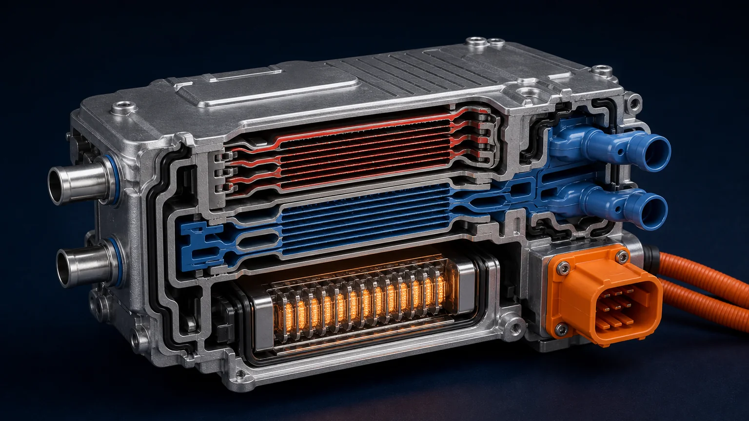
A typical heated chiller combines separate refrigerant and coolant passages with an electrically isolated heater and sensors inside one controlled assembly.
Function 1: battery cooling
During fast charging, high power operation or hot ambient conditions, coolant collects heat from the battery cold plate and flows through the chiller. Refrigerant evaporates on the other side of the heat exchanger and absorbs that heat. The compressor then moves the heat toward the exterior heat exchanger.
Cooling capacity depends on refrigerant mass flow and state, coolant flow, inlet temperatures, heat-transfer area and control. A chiller with the correct port sizes can still have insufficient plate area or the wrong internal circuit. Request capacity and pressure-drop data at defined operating points.
Battery control may prevent condensation or limit coolant temperature gradients. Excessively cold coolant can create local cell stress or moisture risks. The heated chiller follows the vehicle’s requested target; it should not be controlled by a standalone thermostat added during replacement.
Function 2: active battery heating
Cold batteries accept charge and deliver power differently from warm batteries. The integrated electric heater raises coolant temperature so the coolant loop can warm the pack before driving or fast charging. Heat is delivered only when pumps and valves establish the intended flow.
Heater power, voltage range and current are platform-specific. The controller can modulate output according to coolant temperature, battery state, connector temperature, high-voltage limits and available energy. A nominal 400 V or 800 V label is not enough; permitted DC range, power map, inrush, insulation and diagnostics must match.
Dry operation can overheat a heater surface. Air trapped in the coolant circuit reduces heat removal and can trigger local temperature limits. Fill, vacuum-fill or bleed procedures and pump commands must come from service information.
Function 3: cabin heat-pump support
At low ambient temperature, an air-source heat pump has less environmental heat available and may need defrost. A heated chiller can add electrical heat to the coupled refrigerant path, allowing the heat pump to move that energy to the cabin side. This differs from a separate cabin PTC heater that heats air or coolant directly at the cabin.
The advantage depends on system routing and operating conditions. Adding electrical heat does not create free energy; the system still draws battery power. Integration can improve how heat is distributed and can support one compact thermal architecture, but efficiency claims need test conditions.
Valve sequencing, compressor speed, expansion control, pumps and the integrated heater must be coordinated. If the heater activates while refrigerant or coolant flow is wrong, temperatures and pressures can rise locally. Software compatibility is therefore a parts requirement.
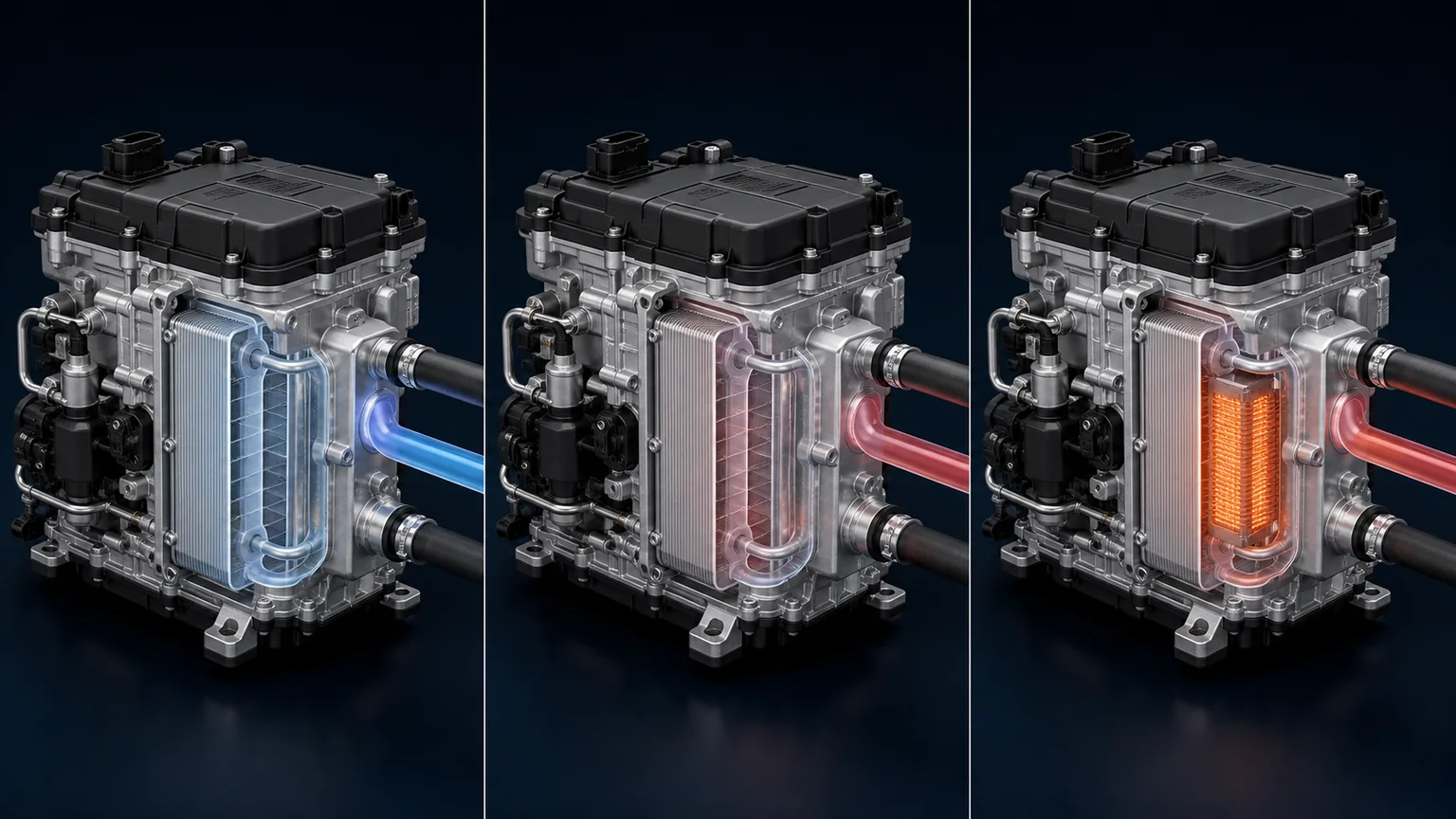
Battery cooling removes heat, active battery heating warms the coolant loop, and cabin-support mode adds controlled heat to the heat-pump energy path.
Four interfaces must match together
Refrigerant interface
Confirm refrigerant, oil, suction/liquid or high/low-side role, port diameter, sealing method, flow direction, pressure and temperature envelope, internal volume and leak specification. R1234yf, R290 and R744 components are not interchangeable. R290 adds flammable-refrigerant containment and service controls; R744 requires high-pressure construction.
Chiller placement relative to the expansion device determines refrigerant state at the inlet. A replacement with different internal distribution can produce maldistribution, noise, excessive superheat or liquid-return risk. Capacity data must use the same refrigerant and boundary conditions.
Coolant interface
Record coolant specification, concentration, allowed conductivity, temperature range, flow/head requirement, port locations, hose connection, degas path and pressure rating. Battery coolant can have tighter electrical and cleanliness controls than conventional engine coolant.
Pressure drop affects pump operating point. A restrictive replacement reduces pack flow; an overly open branch can unbalance parallel circuits. Request a pressure-drop curve across coolant temperature and flow, not one value without viscosity.
High-voltage heater interface
Match DC operating window, continuous and peak heater power, current, connector, polarity, high-voltage interlock, isolation monitoring, precharge or switching behavior and discharge time. The heater may contain power electronics or depend on an external controller.
High-voltage cable length, shielding, terminal plating, seals and strain relief are functional. Do not splice a high-voltage harness or file connector keys to fit. Verify creepage, clearance and grounding/bonding requirements through approved data.
Low-voltage control and sensor interface
The low-voltage connector can carry power, ground, wake, CAN or LIN communication, temperature sensors, interlock or diagnostic signals. Match pinout, voltage, protocol, message identifiers, scaling and hardware/software revision.
Temperature sensors can be integrated at coolant, refrigerant or heater locations. A sensor with the wrong curve can make the controller overheat or underheat the fluid. Position, response time and plausibility diagnostics are part of the design.
Internal separation and cross-leak risk
Refrigerant and coolant exchange heat through metal walls and must remain separate. An internal breach can push refrigerant into coolant or coolant into the refrigerant circuit depending on operating pressures. An electrically heated structure adds an insulation boundary between high-voltage conductors and both fluids.
Validation should address external leakage, refrigerant-to-coolant cross-leak, coolant-to-heater electrical isolation and pressure integrity under temperature cycling. A simple external bubble test does not prove internal separation or dielectric condition.
Possible cross-leak evidence includes changing coolant level, gas in the reservoir, unexplained refrigerant loss, coolant contamination in recovered refrigerant, pressure behavior after shutdown or an isolation fault. These symptoms also have other causes. Use separate circuit tests and fluid analysis before assigning failure.
Valve state, refrigerant response, compressor and cabin delivery
Standby
Isolated or equalized by design
Flow may stop or bypass
Off
Residual voltage, leakage, freeze protection
Fault
Compressor/valves limited or stopped
Protective circulation may continue
Disabled
Fail-safe state, codes and temperature trend
The actual vehicle state table controls service. Some systems may heat battery coolant and support cabin heating simultaneously; others prioritize one load. Do not use a generic state table to command an unsupported mode.
Thermal capacity and electrical power are different
In cooling mode, refrigerant heat-transfer capacity can exceed the electrical input of pumps and control because the compressor drives the refrigeration cycle. In active heating mode, heater electrical power becomes heat, minus distribution losses. In cabin heat-pump support, the system may move added heater energy plus heat collected from other sources.
Request separate maps for battery cooling capacity, coolant heating power and refrigerant-side heat addition. Each should state voltage, refrigerant, fluid flows, inlet temperatures, pressure conditions and ambient. Do not advertise one maximum kW value as all three functions.
Warm-up time depends on battery and coolant thermal mass, heat loss, initial temperature, pump flow and heater limits. A small laboratory loop can warm much faster than a complete vehicle. Fleet acceptance should use representative pack and ambient conditions.
Coolant filling and air management
Integrated passages can trap air. Follow the specified vehicle orientation, vacuum filling, pump activation and valve commands. Fill only with approved coolant and equipment. Mixing coolants can change corrosion protection, conductivity, seal compatibility and freezing behavior.
Watch reservoir behavior, pump speed, flow data and inlet/outlet temperatures. A high heater temperature with little coolant temperature rise suggests low flow or trapped air. Stop rather than repeatedly resetting an overtemperature fault.
After bleeding, verify cold level, pressure integrity and thermal cycles. Inspect hose routing for kinks and high points that trap gas. Ensure clamps and quick connectors are fully seated without loading the chiller ports.
Electrical insulation and fault isolation
Use the vehicle maker’s isolation diagnostic procedure. An isolation code can originate in the heated chiller, compressor, traction battery, inverter, cables, coolant heater or another high-voltage component. Disconnect components only after making the system safe and following the defined sequence.
Insulation test voltage must be approved for the electronics. Applying a generic megohmmeter test can damage semiconductor circuits. Record coolant temperature and condition because conductivity and moisture can affect measurements in fluid-contacting designs.
Inspect high- and low-voltage connectors for moisture, corrosion, tracking, damaged terminals and seals. Check the high-voltage interlock. Do not probe sealed terminals with tools that spread or scratch the contact.
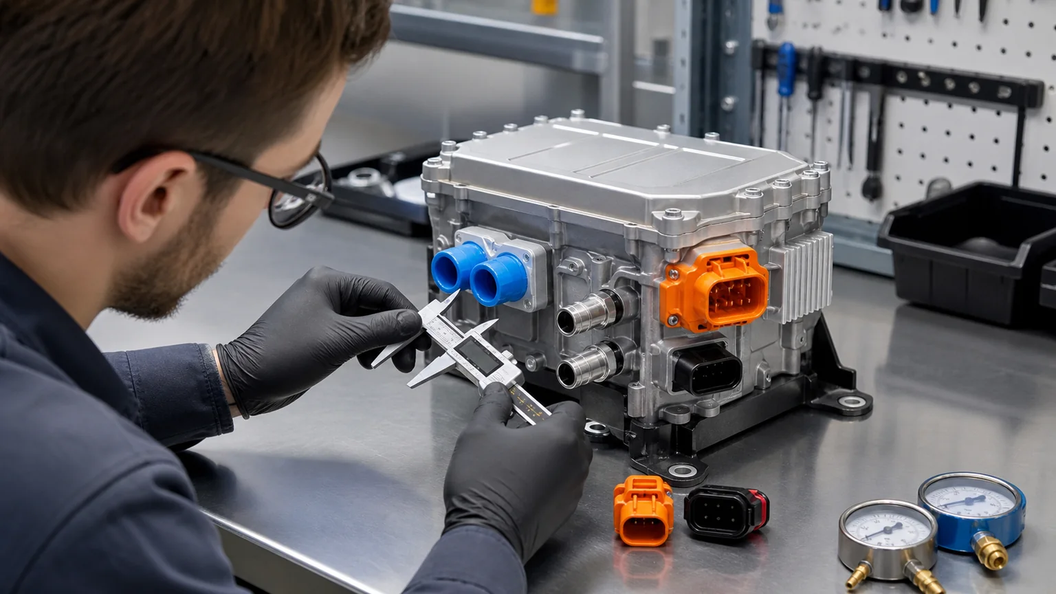
Parts matching identifies refrigerant and coolant ports, high-voltage heater power, low-voltage data, sensors, interlock, flow direction and mounting datums.
Symptom-based diagnosis
Battery cools poorly during fast charging
Check coolant flow, pump command, valve position, chiller inlet/outlet temperatures, compressor speed, refrigerant pressures, expansion control, condenser fan and exterior heat exchanger. A clean heated-chiller label does not rule out a system heat-rejection fault.
Battery heats slowly in cold weather
Compare requested and actual heater power, bus voltage/current, coolant flow, inlet/outlet temperatures, valve state, pack thermal mass and heat losses. Isolation or connector-temperature protection can derate the heater. Air in the loop can create hot spots without useful pack heating.
Cabin heat is weak but battery heating works
The coolant-heating function may be healthy while the refrigerant routing, compressor, expansion device, cabin heat exchanger, air doors or heat-pump control limits cabin delivery. Use the energy path for the requested cabin mode.
Refrigerant loss repeats without an external leak
Consider internal cross-leak with controlled testing. Inspect coolant for compatible evidence and monitor pressure response. Do not open a coolant reservoir if flammable refrigerant contamination is possible until the approved safety procedure addresses the risk.
High-voltage isolation fault appears after coolant service
Review spills, connector moisture, coolant specification and bleeding. Follow the platform isolation sequence rather than immediately replacing the heated chiller. Preserve fluid samples and service records when contamination is suspected.
Passive chiller versus heated chiller
Field
Passive refrigerant-to-coolant chiller
Heated chiller
Primary function
Transfers battery heat to refrigerant
Cools battery, actively heats coolant and supports heat-pump heating
Energy interfaces
Refrigerant and coolant
Refrigerant, coolant, high voltage and control/data
Controls
External valves/pumps/sensors
External system plus integrated heater control/sensing
Main validation
Capacity, pressure drop, leak and cross-leak
All passive tests plus heater power, isolation, temperature and software
Replacement evidence
OE, fluids, ports, pressure/capacity, mounting
All passive fields plus voltage, connectors, protocol, sensors and revision
A passive chiller cannot replace a heated chiller by adding an external resistor. The integrated control and heat path are different. A heated chiller should not replace a passive component unless the vehicle architecture and software were engineered for it.
Incoming inspection and storage
Verify exact OE and module number, hardware/software revision, refrigerant and coolant markings, high- and low-voltage connector keying, port identifiers, mounting, caps and supplied seals. Reject or quarantine impact damage, loose caps, moisture, bent ports or tracked terminals.
Keep refrigerant and coolant passages sealed and dry. Protect high-voltage connectors from electrostatic, moisture and impact damage. Do not use an insulation test, resistance measurement or heater power-up as an uncontrolled incoming check.
Traceability should connect the part to production lot and end-of-line evidence for leaks, cross-leak, heater function, sensors and electrical insulation. Changes to plates, brazing, heater, seals, sensors, electronics or software require notification and impact review.
Replacement and commissioning sequence
Save faults, live data, heater commands, pressures and coolant temperatures.
Make the high-voltage system safe and verify absence of voltage.
Recover the approved refrigerant and drain/contain coolant using separate equipment.
Cap open circuits and compare labels, ports, connectors and mounting.
Install specified new refrigerant seals and coolant connections without tube or hose stress.
Reconnect high- and low-voltage plugs with correct locks, seals and interlock.
Leak-test, evacuate and charge the refrigerant circuit by measured procedure.
Fill and bleed the coolant circuit using commanded pumps and valves.
Run initialization or programming required for the exact revision.
Validate battery cooling, battery heating and cabin-support modes separately.
Recheck leaks, isolation, codes, connector condition and fluid levels.
RFQ fields
VIN, platform, production date and thermal-system supplier.
Complete OE/module number and hardware/software revision.
Refrigerant, oil and pressure/temperature envelope.
Coolant specification, flow, pressure drop and port details.
High-voltage DC range, heater power, current, connector and interlock.
Low-voltage supply, pinout, CAN/LIN protocol and sensor curves.
Cooling capacity, coolant heating and cabin-support test points.
Refrigerant/coolant cross-leak and electrical-isolation evidence.
Mounting, orientation, package envelope and supplied seals.
Initialization, programming, service and safety requirements.
Quantity, destination, packaging, labeling and traceability.
Related heat-exchanger categories such as an automotive oil cooler, wholesale A/C condenser or A/C condenser use familiar plate or tube-and-fin principles, but none should be cross-referenced to a heated chiller without the full multi-energy validation.
Final approval checklist
For fleet validation, log battery inlet/outlet coolant temperatures, chiller refrigerant conditions, heater request and actual power, pump flow evidence, compressor speed, ambient temperature, charging state and fault limits in each operating mode. Tie the results to the exact module and vehicle software revision. Seasonal field data can reveal air-management, connector or control problems that a short workshop test does not reproduce.
The exact vehicle, module and software revision are matched.
Refrigerant and coolant ports, flow direction and seals are identified.
Cooling, battery-heating and cabin-support capacities meet defined conditions.
DC range, heater power, connector, interlock and insulation match.
Low-voltage pinout, protocol, sensors and diagnostics match.
Pressure drop, external leak and cross-leak requirements pass.
Mounting, orientation and hose/tube stress are correct.
Coolant filling and air-bleeding procedures are available.
High-voltage and refrigerant service requirements are controlled.
No passive-chiller or heater retrofit is assumed without engineering approval.
Key conclusion: an EV heated chiller integrates battery cooling, active coolant heating and heat-pump support inside one controlled component. The extra function adds high voltage, electronics and insulation to the refrigerant/coolant boundary. Exact OE mapping, four-interface compatibility, cross-leak evidence and software-controlled commissioning are required before replacement.
For parts support, send the original module label and clear photographs of every fluid port, connector, mounting face and surrounding circuit before requesting a cross-reference.