You are here:Home » Blog » Technical Guides » Compact 5-Way Refrigerant Valves for EV Heat Pumps: Port Mapping, Actuation, and Parts Matching
Compact 5-Way Refrigerant Valves for EV Heat Pumps: Port Mapping, Actuation, and Parts Matching
Views: 0 Author: Elecdura Publish Time: 2026-09-01 Origin: Site
A compact five-way refrigerant valve is not interchangeable because another valve has five ports. Replacement requires the exact port-to-port flow map for every commanded state, refrigerant and oil compatibility, pressure and temperature envelope, actuator type, position feedback, connector and communication protocol, internal leakage limits, response time, fail-safe position, mounting orientation and control-software compatibility. A wrong state map can route high-pressure gas or liquid refrigerant toward the wrong heat exchanger.
Integrated valves reduce the number of discrete solenoid valves, check valves, tubes, connectors and joints inside an EV heat-pump module. That compactness improves package efficiency but concentrates several functions in one component. Matching must therefore connect the valve to the electric A/C compressor, exterior heat exchanger, cabin heat exchanger, battery chiller, accumulator and controller as one refrigerant architecture.
Service boundary: refrigerant recovery, charging, leak testing and electric-vehicle thermal-system work require trained personnel, approved equipment and vehicle-specific information. R290 versions add flammable-refrigerant controls; high-voltage compressors add isolation procedures. Do not bench-route refrigerant through an unidentified valve.
What an integrated five-way valve changes
A conventional reversible heat-pump circuit can use several on/off solenoid valves plus check valves to select cooling, heating, battery conditioning and defrost paths. Each valve has a coil, connector, joint and potential leak point. An integrated rotary or sliding valve can combine several routes inside one sealed body and move between them with one actuator.
Valeo announced a compact five-way refrigerant valve that replaces three solenoid valves and one check valve in its smart heat-pump module. Its rotating plate aligns internal channels and is described as changing modes in under five seconds. Valeo also states an operating temperature span of −40°C to +105°C and compatibility with R1234yf and R290 for that specific design, with series production announced for September 2026.
Those published attributes belong to the named design, not all five-way valves. Another supplier can use a spool, disk, rotary plug or multiple internal seats, with different ports and electrical behavior. Buyers should treat “five-way” as a functional category and require part-specific evidence.
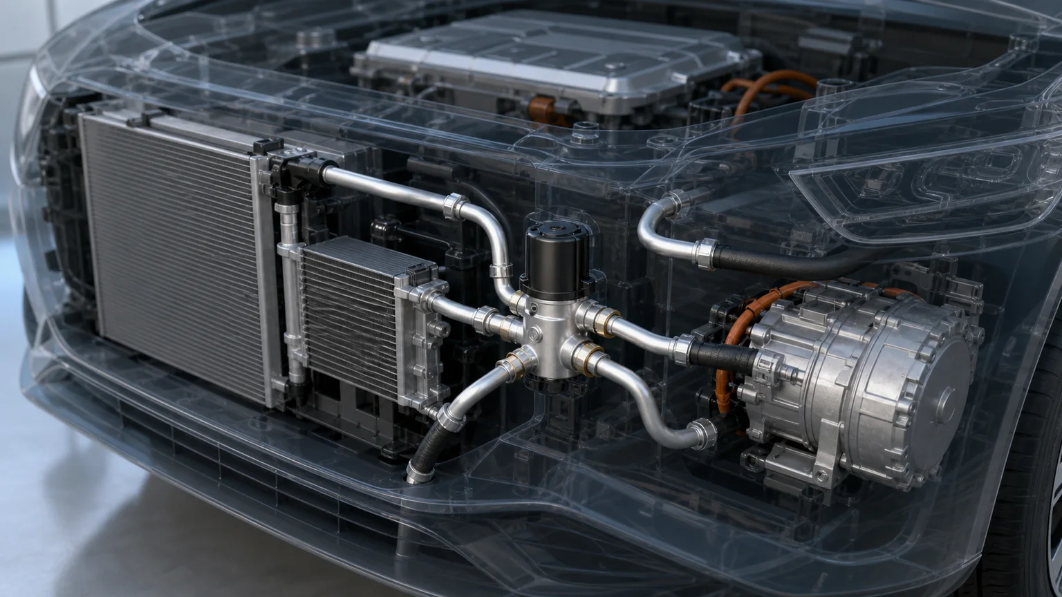
A compact multi-way valve sits between the compressor and several heat exchangers; each physical port must be identified by circuit function and refrigerant state.
Five physical ports do not define five functions
A port is only an opening. Its function depends on which internal channel reaches it at a given actuator position. Port A might connect to compressor discharge in one design and to an exterior heat exchanger in another. Port lettering can be arbitrary and may change between castings or revisions.
One valve position can connect two port pairs while isolating the fifth. Another can join three ports and close two. A design can also include an internal check function, controlled bleed or pressure-balancing passage. Counting open ports from a photograph cannot reveal these relationships.
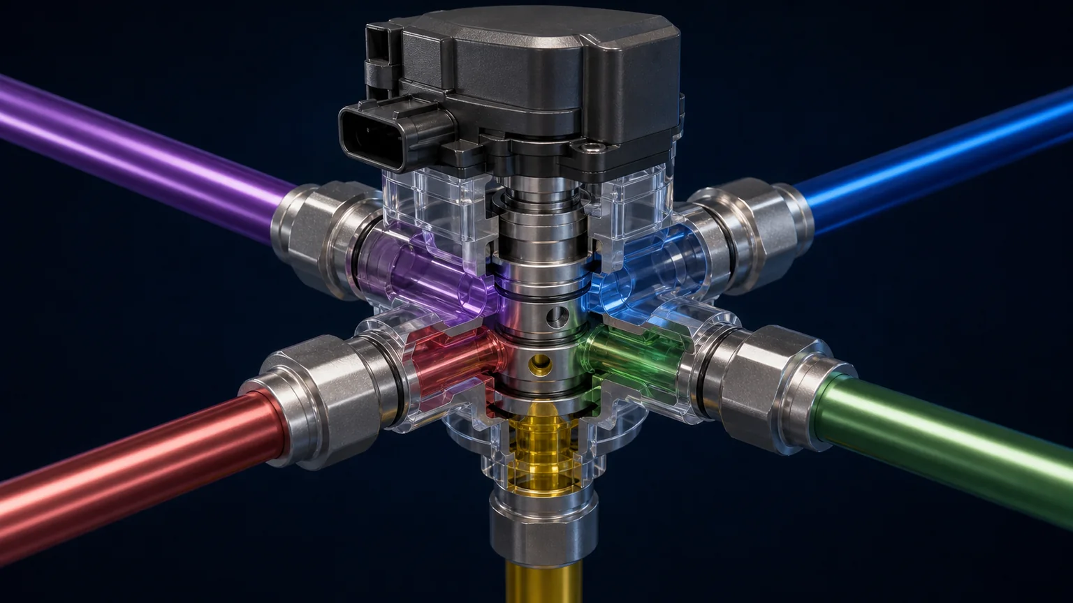
Obtain a state table or schematic from the approved service information. It should identify every port by circuit destination and show open, closed and check-flow relationships for each commanded mode. If the drawing uses color, preserve labels because printed or scanned copies may lose color distinctions.
Flow direction matters. A path that permits gas in one direction may contain a check function against reverse flow. Internal pressure forces can assist or oppose actuator motion. Reversing inlet and outlet may change leakage or prevent the valve from reaching position under load.
Typical operating states
Cabin cooling
The compressor sends hot high-pressure vapor toward an exterior heat-rejection exchanger. Condensed refrigerant then passes through a metering device and absorbs cabin heat at an evaporator or refrigerant-to-coolant chiller. Battery cooling may share the evaporating side when the controller requests it.
Cabin heating
Valve routing changes so compressed refrigerant releases heat to the cabin-side exchanger or coolant loop. The exterior exchanger or another thermal source supports evaporation. The multi-way valve must keep discharge, liquid and suction paths correctly separated.
Battery cooling during charging
The battery chiller becomes a priority load while cabin demand may be low. The controller can vary compressor speed, expansion and valve state to maintain battery coolant temperature. A valve with excessive internal leakage can reduce capacity or send unwanted heat into another branch.
Battery heating and waste-heat recovery
Some platforms recover heat from motors and power electronics through a coolant loop and deliver heat to the battery or cabin. Refrigerant and coolant valves cooperate. A five-way refrigerant valve must not be confused with a multi-port coolant valve even if the housings look similar.
Defrost
When an exterior evaporator accumulates frost, the system can temporarily reverse or redirect heat. Defrost routing and timing protect visibility, cabin comfort and components. The valve must change state reliably at low temperature and under pressure differential.
Actual platforms can use more or fewer modes, and some transitions pass through an intermediate pressure-balancing state. The service state table controls diagnosis. A generalized diagram must be marked typical and cannot authorize hose routing.
A state map links named circuit destinations—not just port numbers—for cooling, heating and defrost, while showing isolated and permitted one-way paths.
Mechanical matching fields
Port position and sealing
Record the center coordinates and angle of each port from defined datums. Compare tube diameter, manifold pattern, threads or brazed joint, sealing seat, O-ring groove, insertion depth and retaining method. Similar aluminum bodies can place internal passages differently.
Use only specified seals and lubricants. Refrigerant seals must tolerate the fluid, oil, pressure cycling and temperature. A thicker O-ring can prevent full tube insertion; a thinner one can leak. Surface scratches, corrosion and burrs at a seal land are rejection evidence.
Mounting and orientation
Match mounting holes, bracket stiffness, isolators and installed angle. Orientation can influence oil or liquid accumulation, actuator load and service access. A valve must not be suspended by refrigerant tubes or forced into alignment by tightening fasteners.
Package and thermal environment
Measure maximum body and actuator envelope, connector swing, tube clearance and proximity to high-voltage cables or heat sources. Confirm the operating and storage temperature ranges. Underbody locations also require water, salt, debris and impact protection.
Internal volume and flow capacity
Compact refrigerant charge depends partly on internal volume. Flow passage size and geometry determine pressure loss. Request pressure-drop data for each relevant route at stated refrigerant condition and mass flow. One route can be more restrictive than another.
Actuator, sensor and control matching
An integrated valve can use a brushless motor, stepper motor, geared DC motor or another actuator. The controller may command position through LIN, CAN, PWM, step/direction or polarity reversal. It can receive position through an internal sensor, step count, current signature or network response.
Connector shape and pin count do not establish protocol. Match low-voltage supply range, ground, wake, pinout, communications, message identifiers, scaling, update rate, diagnostic behavior and software revision. A valve that moves with a bench supply can still report the wrong position to the vehicle.
Position resolution matters because the valve may use discrete detents or controlled intermediate states. Mechanical stops, indexing and actuator zero must agree with software. Installing the actuator one tooth out can make the reported state disagree with the actual channels.
Response time is defined under load and temperature. A valve that moves freely at room temperature may stall at −30°C or against a high pressure difference. Current limiting and fault detection should distinguish normal high-load movement from obstruction.
Fail-safe behavior must be known
Loss of power or communication can leave the valve in its last position, drive it to a spring-return state, or command a defined safe route while low-voltage power remains. The correct behavior depends on platform hazards. It may prioritize compressor protection, battery cooling, pressure equalization or refrigerant containment.
Do not call one position universally “normally open.” Multi-way valves have several simultaneous paths. A useful fail-safe description states which circuit ports connect, which isolate, and under what power-loss or fault condition.
The controller should detect position disagreement, movement timeout, overcurrent, communication loss and implausible pressure/temperature response. Fault handling can stop the compressor or limit thermal operation. An aftermarket valve must support the expected diagnostics.
Refrigerant and material compatibility
R1234yf and R290 have different safety classifications, yet a specific valve may be engineered for both. Compatibility requires validated seals, polymers, metals, lubricant interaction, permeation, pressure/temperature limits and leakage. A material name such as PTFE does not establish the full assembly result because filler, geometry, surface finish and preload matter.
R744 uses a much higher pressure architecture and requires a purpose-designed valve. Do not repurpose a low-pressure refrigerant valve because the ports can be adapted. Likewise, do not convert a vehicle between refrigerants by replacing the valve and compressor alone.
R290 adds flammability controls around charge, component placement, joints, leak paths, detection, ventilation and service equipment. Compatibility printed on a component is necessary but does not replace vehicle-level approval.
Leakage has external and internal forms
External leakage releases refrigerant through a body joint, port seal, actuator penetration or casting. Test method, medium, pressure, temperature and leak threshold should be specified. Packaging and handling must protect sealing faces from damage that produces later leakage.
Internal leakage passes across a closed seat or between channels. It may not lose refrigerant to atmosphere, but can reduce heating/cooling capacity, slow pressure equalization, warm an inactive exchanger or create an implausible sensor pattern. Each valve state can have a different internal-leakage limit.
Testing only one pressure direction can miss a check-valve or differential-pressure issue. A validation plan should cover routes, directions and temperatures required by the design. Production end-of-line testing may combine external leak detection, actuator movement and route verification.
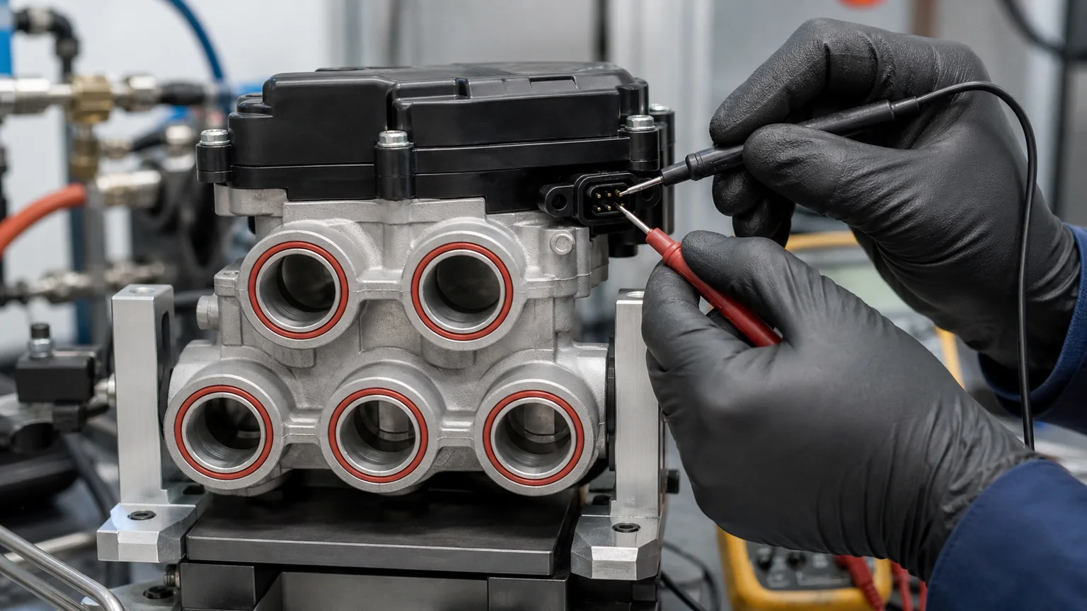
Controlled testing verifies port identity, commanded position, feedback, pressure decay and internal isolation for each required route without energizing an unknown pinout.
Controlled bench validation
A safe fixture positively identifies all ports, uses compatible regulated test media, rated hoses and remote control, and prevents uncontrolled stored energy. The electrical controller applies the correct supply and protocol. Pressure transducers confirm that the commanded path opens and isolated paths remain within leakage limits.
Route testing can begin at a low safe differential to confirm mapping, then follow the specified pressure and temperature matrix. Record command, actual position, transition time, actuator current, inlet pressure, outlet pressure, leakage and temperature. Test intermediate states only when the design permits them.
Do not use shop air with refrigerant oil or residual flammable refrigerant. Do not apply battery voltage to guessed pins. A basic continuity meter cannot identify a networked actuator and may not safely evaluate its electronics.
After environmental or endurance tests, repeat route and leakage checks. Temperature cycling, pressure pulsation, vibration, salt exposure and actuator cycling can reveal failures not present on a new sample.
Diagnosis on the vehicle
Identify the requested mode. Record cabin, battery and charging demand plus ambient conditions.
Read faults and live data. Save commanded valve state, actual feedback, compressor speed, pressures, refrigerant and coolant temperatures.
Command approved state changes. Listen or feel only from a safe position and observe feedback and pressure/temperature response.
Separate valve from system faults. A blocked heat exchanger, weak pump, wrong charge, faulty sensor or compressor limit can mimic bad routing.
Open the circuit only when justified. Recover refrigerant and follow platform safety procedures before removal.
A valve position code does not always prove mechanical failure. Low supply voltage, network faults, an obstructed actuator, pressure load, calibration, ice or control-software mismatch can prevent movement. Compare command, feedback, current and thermal response.
Five-way valve matching matrix
Field
Required evidence
Wrong-match consequence
OE/revision
Exact part number, vehicle and software cross-reference
No communication or wrong thermal modes
Port map
Named destinations and open/closed/check paths by state
Misrouted high/low side
Pressure/flow
Envelope and route-specific pressure-drop data
Leakage, restriction or rupture
Refrigerant/oil
Assembly-level compatibility
Seal damage, permeation or safety failure
Actuator
Motor type, indexing, torque and transition time
Stall or incorrect state
Electronics
Pinout, voltage, CAN/LIN/PWM and diagnostics
Damage or no control
Fail-safe
Port relationships after defined fault/power loss
Compressor or battery risk
Mechanical
Ports, seals, brackets, orientation and envelope
Leak, tube stress or interference
Incoming inspection for distributors
Keep ports capped and the connector protected until installation. Verify part and revision labels, casting marks, port identifiers, cap condition, sealing surfaces, mounting, connector keying and included seals. Quarantine valves with impact marks, bent tubes, moisture or loose caps.
Master data should include a port drawing with vehicle-side destinations, not only A–E lettering. Store the actuator protocol, refrigerant, pressure/temperature range and supported OE cross-references. Link every unit to a production lot and test record.
Do not rotate a shaft, plate or actuator manually unless service information permits it. Forcing it can damage gears, lose calibration or scratch a seal. Do not remove an actuator to inspect the internal plate on a warranty unit.
Replacement and commissioning sequence
Save diagnostic codes, commanded and actual valve states, pressures and temperatures before recovery. Make the high-voltage system safe when the platform procedure requires it, recover the correct refrigerant with approved equipment, then cap every open line immediately. Compare the removed and replacement labels, port map, actuator index and mounting before disturbing shipping caps.
Install new specified seals on clean, undamaged seats. Support tubes so fasteners do not pull them sideways into alignment. Tighten the valve and line joints in the stated sequence and torque. Reconnect the electrical plug only after checking dry terminals, seal position and latch engagement.
Complete leak testing, evacuation and measured charging according to the refrigerant and platform. Run any valve initialization or learned-position routine. Command each permitted thermal mode while monitoring position feedback, pressures, compressor behavior, refrigerant and coolant temperatures and related faults. A successful actuator sound is insufficient; the measured energy path must agree with the commanded route.
After stabilization, inspect for leakage, line vibration and connector stress, then save the post-repair diagnostic record. For R290, retain all flammable-refrigerant safety and workshop controls through the final leak check and equipment disconnection.
RFQ and supplier questions
Which OE number, vehicle platform and hardware/software revision are supported?
What named circuit destination connects to each physical port?
Which paths are open, closed or check-controlled in every commanded state?
What are the refrigerant, oil, pressure and temperature limits?
What pressure drop and internal leakage apply to each route?
What actuator, supply, connector, pinout and communication protocol are used?
How is position measured and calibrated?
What is the transition time under pressure and at temperature extremes?
What happens after power loss, communication loss or position disagreement?
Which seals and mounting hardware are included?
What leak, route, endurance and environmental tests support the part?
What quantity, destination, packaging and traceability can be supplied?
Every port is mapped to a named component and state.
Open, closed, check-flow and fail-safe paths are documented.
Refrigerant, oil, seal, pressure and temperature compatibility are verified.
Route-specific pressure drop and leakage meet requirements.
Actuator, connector, pinout, protocol and feedback match.
Mounting, orientation, envelope and tube stress are acceptable.
Leak and route tests cover the complete production assembly.
Service equipment and safety controls match the refrigerant and EV platform.
No hose, wiring or software adapter is assumed without engineering approval.
Key conclusion: an EV five-way refrigerant valve replaces several discrete routing functions, so its value and risk are both concentrated. Exact port mapping, actuator and software compatibility, internal isolation, refrigerant materials and fail-safe behavior must all match. Port count, body shape and connector appearance cannot establish interchangeability.