You are here:Home » Blog » Technical Guides » Oil-Free E-Cooling Compressors for Electric Buses and Trucks: 400V-800V Architecture and Aftermarket Boundaries
Oil-Free E-Cooling Compressors for Electric Buses and Trucks: 400V-800V Architecture and Aftermarket Boundaries
Views: 0 Author: Elecdura Publish Time: 2026-09-01 Origin: Site
An oil-free foil-bearing centrifugal e-cooling compressor is not a drop-in substitute for a scroll electric A/C compressor. It uses an ultra-high-speed motor, impeller, gas-film bearing system and dedicated inverter control. Safe integration requires the exact refrigerant, 400–800 V electrical window, aerodynamic operating map, pressure ratio, mass flow, surge and speed limits, connector and communication protocol, thermal mounting, noise/vibration design and vehicle control calibration.
The architecture is emerging for electric buses and trucks, where cabin volume, battery fast charging, passenger load, long operating hours and heat-pump duty create demanding thermal loads. It expands the future electric A/C compressor landscape, but early serial programs are system-engineered integrations rather than universal aftermarket replacements.
Terminology: an e-cooling compressor moves refrigerant for HVAC and thermal management. It is different from an electric air compressor for brakes, a fuel-cell air compressor, a coolant pump and a turbocharger. Confirm the working fluid and circuit before interpreting a product name.
What the announced commercial-vehicle architecture includes
Garrett Motion announced in February 2026 that Cling selected its oil-free, foil-bearing centrifugal compressor for next-generation electric bus and truck HVAC systems in China, with production expected in 2027. Garrett describes a motor speed above 160,000 rpm, support for 400–800 V heat-pump systems, compatibility with low-pressure low-GWP refrigerants and up to 45,000 hours of maintenance-free operation under its validation program.
The announcement also reports up to 50% smaller size, 30% lower mass and 10 dB lower noise than traditional scroll compressors for the referenced technology comparison. These are supplier-specific development claims, not universal values for every centrifugal compressor or operating point. Purchasing specifications should use the final program data and defined comparison conditions.
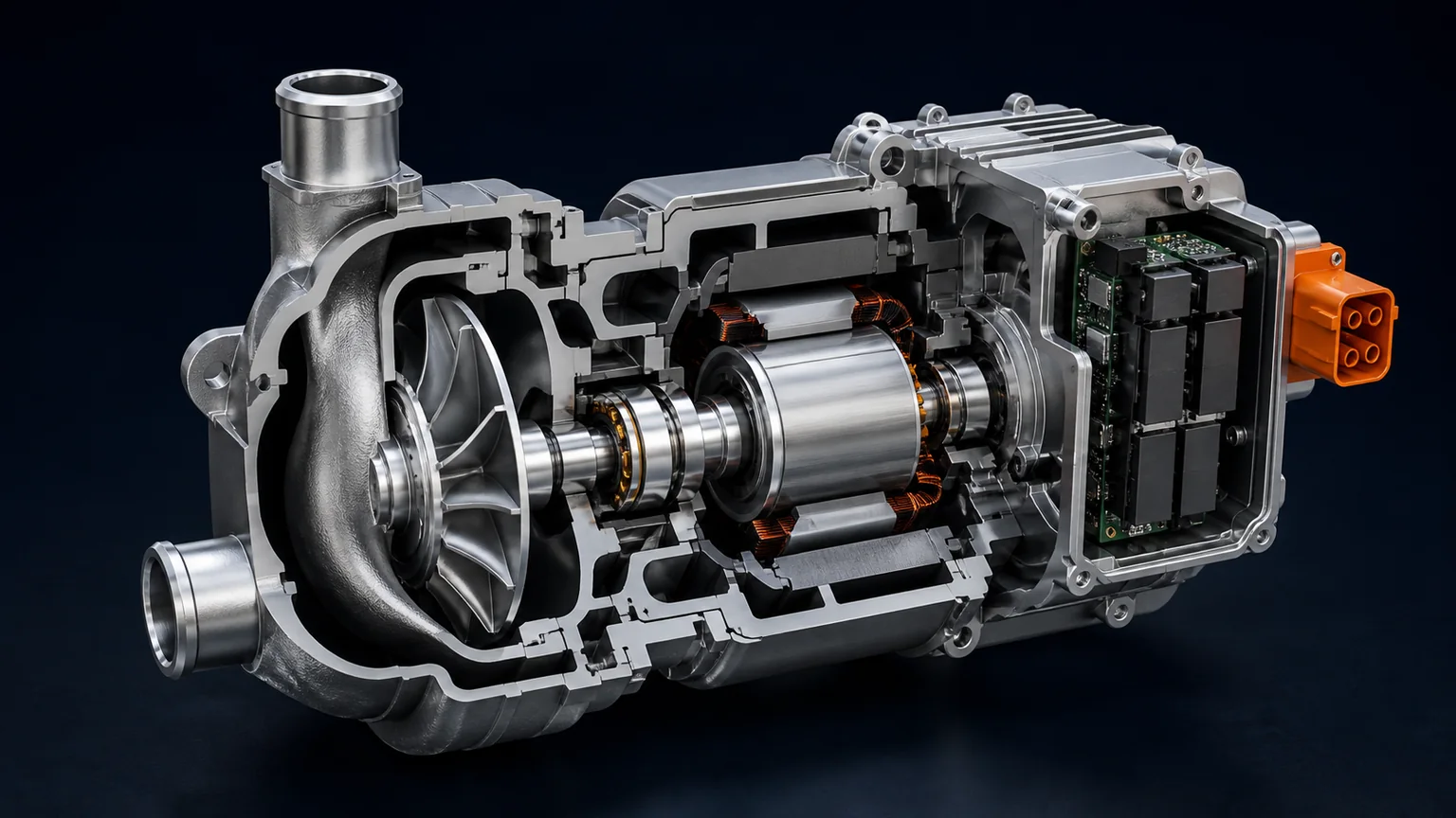
The significant change is mechanical: the refrigerant compressor uses turbomachinery principles familiar from high-speed air systems but adapts them to a closed vapor-compression circuit and automotive production. The inverter, impeller, motor, bearings and thermal controller are designed together.
A typical architecture combines a high-speed impeller, electric motor, foil bearing support, diffuser/volute and inverter without a conventional circulating oil system.
Scroll and centrifugal compression work differently
Scroll compressor
A scroll compressor traps refrigerant between fixed and orbiting scroll elements and reduces the pocket volume toward the discharge. It is a positive-displacement machine: refrigerant flow is closely related to displacement and speed, although leakage, pressure ratio and control limits affect delivered flow.
Electric scroll compressors are established across passenger and commercial EV platforms. They usually rely on specified oil for scroll, bearing and sealing functions, and the oil circulates with refrigerant. System design supports oil return across different loads and line arrangements.
Centrifugal compressor
A centrifugal stage accelerates refrigerant through a high-speed impeller. The diffuser and volute convert velocity into pressure. It is a dynamic compressor, so flow and pressure rise depend on speed, inlet state, impeller geometry and system resistance. Its operating map has boundaries that cannot be described by displacement alone.
High rotational speed allows a compact impeller to process the required flow. The motor and inverter must control speed precisely, and the refrigerant circuit must keep operation away from unstable low-flow behavior and excessive high-flow conditions. A controller written for a scroll compressor cannot simply command the same rpm.
How foil bearings enable oil-free operation
A gas foil bearing uses compliant metal foils around the shaft. During rotation, a thin pressurized gas film develops and supports the shaft without conventional liquid-oil lubrication in the bearing interface. The compliant structure accommodates small movement and provides damping.
At rest and during very low-speed start or stop, a full hydrodynamic gas film may not yet exist. Bearing surface coatings, foil design, rotor balance and the acceleration/deceleration strategy manage those transitions. Start-stop durability is therefore a controlled system property, not proof that the bearing is frictionless in every state.
Oil-free means the refrigerant circuit avoids the conventional compressor lubrication loop. It does not mean the product has no friction, wear mechanism or maintenance requirements elsewhere. Connectors, seals, electronics, cooling paths and filtration/cleanliness remain important. The manufacturer’s claimed maintenance interval applies under its defined validation conditions.
Why oil-free refrigerant circuits matter
Oil carried through heat exchangers can create a film that changes heat transfer and pressure drop. System designers also need separators, return velocity and routing that reliably bring oil back to the compressor. Removing circulating lubricant can simplify some of those constraints and reduce sensitivity to oil distribution.
An oil-free circuit is not automatically compatible with components from an oil-circulating system. Heat exchangers, hoses, seals, expansion devices and manufacturing processes may contain residual oil. Service machines and recovered refrigerant can cross-contaminate the circuit. Cleanliness specifications must state permitted residues.
Do not add dye or oil to quiet an unfamiliar compressor. The correct response to noise or a fault is to capture speed, pressure, temperature, current, vibration and control data, then follow the system supplier’s diagnostic procedure.
Commercial vehicle thermal loads
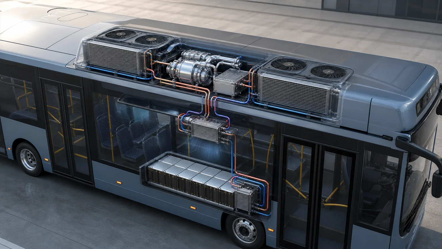
An electric bus combines a large cabin, frequent door opening, high passenger density and long daily service. Solar load and humidity can vary by route. The thermal system may also cool the traction battery, inverter, motor and charging electronics while supporting heat-pump heating.
Electric trucks add cab comfort, sleeper operation, battery conditioning and sometimes cargo or transport-refrigeration loads. These circuits may be separate. A transport refrigeration compressor cannot be assumed to serve the vehicle cabin or battery loop.
High-power charging produces a strong battery-cooling demand while the vehicle is stationary. Exterior heat-exchanger airflow depends on electric fans rather than road speed. Compressor capacity must be coordinated with fan, condenser/gas cooler, chiller, coolant-pump and valve performance.
Cold-weather operation can require cabin and battery heating. Pressure ratio and discharge temperature rise as ambient conditions become more difficult. The centrifugal map, heat-pump routing and defrost strategy must remain stable across that range.
The compressor works with the exterior heat exchanger, cabin coil or coolant heater core, battery chiller, pumps, valves and fans across cooling, heating and charging modes.
The centrifugal operating map controls selection
A useful map shows corrected or actual mass flow versus pressure ratio across speed lines, with efficiency and operating boundaries. Refrigerant inlet temperature and pressure must be stated. Different refrigerants and conditions change density, sound speed and aerodynamic behavior.
At too little flow for a given pressure ratio, the compressor can approach surge or another unstable region. Flow and pressure oscillate, creating noise, vibration and control stress. At excessive flow, the stage can approach choke or reach motor and speed limits. The vehicle controller stays within a validated envelope.
Map matching covers every operating mode, including startup, cabin pull-down, battery fast-charge cooling, heat-pump heating, defrost and low-load modulation. A compressor selected only at the maximum cooling point can operate poorly during mild-weather part load.
System restriction changes the operating point. A blocked exterior heat exchanger, incorrect expansion command, closed valve or wrong refrigerant charge can move the compressor toward a boundary. Protective control may reduce speed or shut down before physical damage occurs.
400–800 V integration
Support for a broad voltage architecture does not mean one production part accepts every voltage without configuration. Request the exact DC input range, continuous and peak electrical power, precharge behavior, current limits, isolation requirement, high-voltage connector, interlock and discharge time.
The inverter drives an ultra-high-speed motor and must account for back electromotive force, switching losses, rotor dynamics and thermal limits. Hardware and software revisions are inseparable from compressor performance. Replacing only an inverter or motor with an unapproved variant can invalidate balance and control.
Low-voltage interfaces carry supply, wake, CAN or another network, diagnostics and possibly coolant-valve or sensor integration. Connector keying and pinout must match. Cybersecurity or controller authentication may be part of serial vehicle programs.
Refrigerant and heat-pump compatibility
“Low-pressure, low-GWP refrigerant” is not an interchangeable fluid category. Final program documentation must name the refrigerant, pressure/temperature envelope and material compatibility. R1234yf and R290 require different safety controls; R744 uses a much higher-pressure architecture.
Impeller and diffuser geometry are refrigerant-specific because molecular properties affect flow and pressure rise. Changing refrigerant shifts the operating map and motor load. Seals, motor materials and inverter cooling also require validation.
For R290, flammability changes charge management, containment, component placement, ventilation, detection and service equipment. Oil-free operation does not remove the refrigerant hazard. For mildly flammable fluids, platform-specific workshop requirements still apply.
Rotor dynamics, balance and noise
At speeds above 160,000 rpm in the announced design, small imbalance can create significant force. Rotor manufacturing, assembly, high-speed balancing, bearing geometry and housing stiffness are critical. An impact that leaves the exterior intact can still affect the rotating group.
Do not disassemble, straighten or clean the impeller with workshop methods. Dust, metal particles or a damaged inlet can disturb the aerodynamic and balance condition. Shipping ports should remain sealed and protected from foreign objects.
Noise evaluation should link frequency to shaft speed, electrical switching, flow instability and mounting resonance. Overall dB alone can hide a narrow tonal peak. Record operating condition, speed command, pressures, microphone location and background.
Vehicle brackets and isolators control transmitted vibration. A lighter compressor changes structural response, so bracket design is part of integration. Do not fabricate a flat adapter plate and assume it preserves durability.
Cooling the motor and inverter
High-speed electrical conversion produces heat in motor windings, rotor, bearings and power electronics. Cooling may use refrigerant, a coolant circuit, the housing or a combination. Record all coolant ports and flow requirements separately from refrigerant ports.
Insufficient coolant flow can trigger derating that resembles a refrigerant-capacity problem. Compare inlet/outlet coolant temperatures, pump command, flow or pressure evidence and inverter temperature. Air trapped in a liquid-cooling circuit can reduce heat transfer.
Coolant chemistry, electrical conductivity, corrosion inhibition and seal compatibility must match the platform. Never connect a coolant line to an unidentified port because its diameter resembles a hose barb.
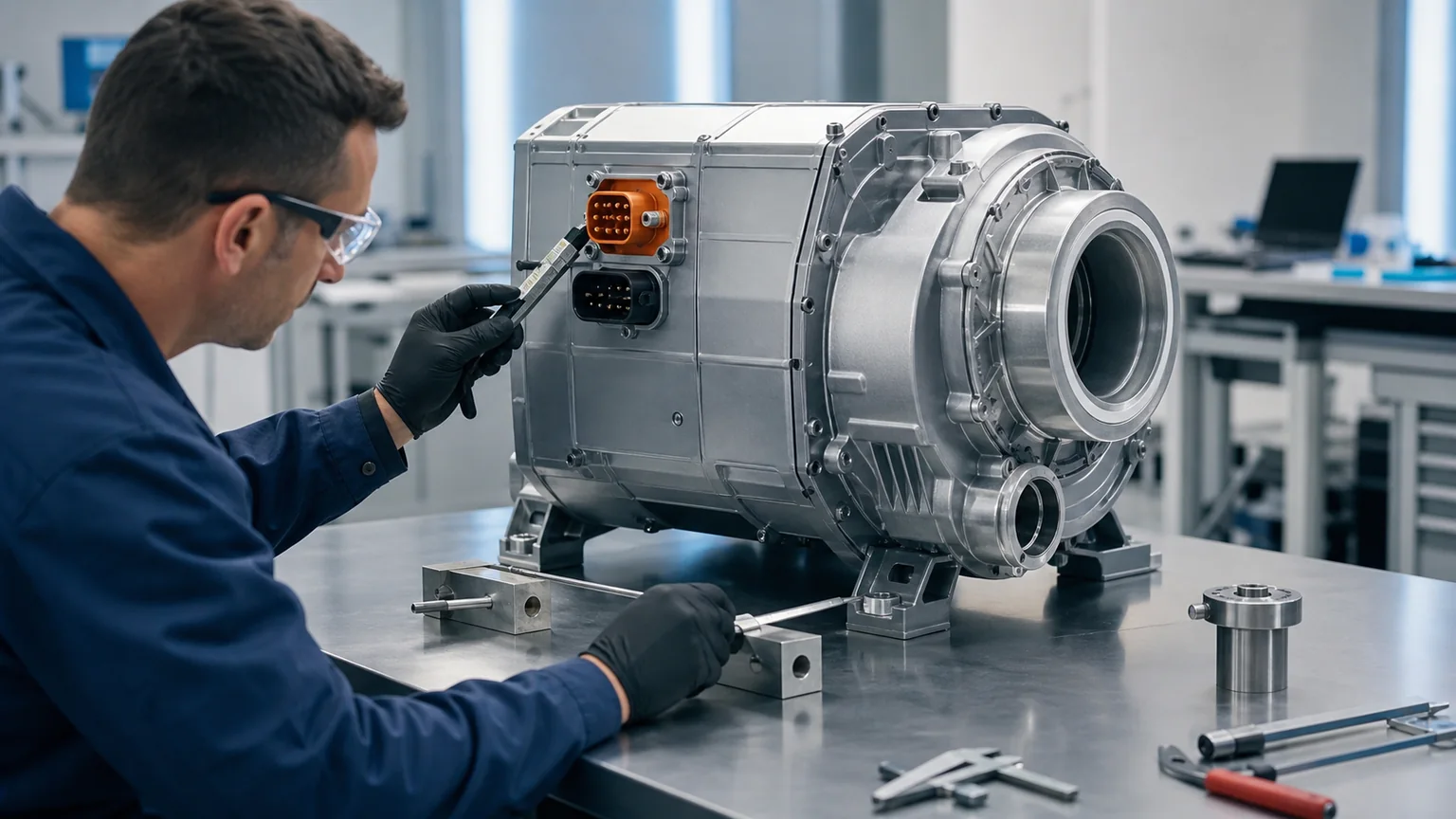
Identify high-voltage power, low-voltage data, refrigerant inlet/discharge, any electronics-coolant ports, mounting and revision labels before parts approval.
Aftermarket and service boundaries
Early oil-free centrifugal units may be supplied only as part of an integrated HVAC or heat-pump module. Service information can restrict replacement to a sealed compressor/inverter assembly or a larger module to preserve cleanliness, calibration and warranty. Availability of a component image does not prove individual serviceability.
Parts matching requires the vehicle and thermal-system supplier, exact OE number, hardware/software revision, refrigerant, voltage, operating map, connectors, port geometry and mounting. A conventional truck A/C compressor listing cannot establish a centrifugal replacement.
Remanufacturing demands high-speed rotor and foil-bearing expertise, inverter test capability, clean assembly and program-specific software. Replacing bearings by size or repainting a housing is not a credible process. Request end-of-line evidence at representative speed and load.
Workshop repair may focus on approved external items such as harness, seals, coolant lines or mounting, depending on service data. Opening the refrigerant circuit, powering the inverter or disassembling the rotating group requires authorized procedures and equipment.
Diagnostic sequence
Identify the operating complaint and mode. Cabin cooling, battery cooling, heating and charging create different targets.
Save faults and revision data. Record vehicle, thermal controller, inverter and compressor identifiers.
Read commands and feedback. Capture speed request/actual, bus voltage/current, pressures, temperatures and derating flags.
Check the rest of the system. Confirm fans, heat exchangers, coolant pumps, expansion devices, valves and charge evidence.
Inspect interfaces safely. After approved isolation, check connectors, interlock, ports, coolant routing, mounts and impact.
Compare the operating point with approved limits. Surge protection or thermal derating may be a response to another fault.
Preserve evidence before removal. Do not open the compressor or contaminate capped ports.
Architecture comparison
Field
Electric scroll
Oil-free centrifugal
Compression principle
Positive displacement through orbiting scroll pockets
Dynamic pressure rise through high-speed impeller and diffuser
Flow control
Primarily speed, displacement and pressure conditions
Speed plus aerodynamic map and system resistance
Lubrication
Specified oil circulates with refrigerant
Foil-bearing gas film; no conventional circulating oil in announced design
Main selection evidence
Displacement/speed map, oil, voltage, refrigerant and control
Mass-flow/pressure-ratio map, speed boundaries, voltage, refrigerant and control
Key protection
Oil return, temperature, pressure and electrical limits
Surge/choke avoidance, rotor speed, temperature, vibration and electrical limits
Service outlook
Established but platform-specific
Emerging, likely system-controlled and initially narrow
Interpreting common field observations
Repeated low-flow or surge protection: inspect the requested thermal mode, expansion control, refrigerant charge evidence, valve routing and heat-exchanger condition before condemning the compressor. A restriction or control error can push a healthy unit toward an unstable map boundary. Save the command, actual speed, suction/discharge conditions and protection counter.
High inverter temperature with limited refrigerant capacity: check electronics-coolant flow where used, coolant bleeding, pump command, connector resistance, bus voltage and ambient heat soak. Derating can intentionally reduce shaft speed. Replacing the refrigerant side without restoring inverter cooling will repeat the symptom.
New tonal noise after impact or service: stop operation if vibration rises or the supplier’s limits are exceeded. Inspect mounts, brackets, lines and shipping/foreign-object controls. Do not attempt to rebalance the rotating group in a general workshop. Provide speed-resolved sound and vibration evidence to the system supplier.
Capacity differs after a software update: compare control revisions, compressor speed limits, valve strategy and battery-protection priorities. The hardware can be healthy while a revised calibration changes available thermal power under defined energy or temperature conditions.
Isolation or communication fault: follow the high-voltage diagnostic sequence, including interlock, connector, low-voltage supply, network and approved isolation measurements. Do not inject voltage into unknown pins or infer a failed inverter from one general vehicle code.
Fleet reports should link each event to route, passenger or cargo load, ambient condition, charging state, vehicle and thermal software, operating hours and the exact compressor revision. Aggregated evidence can separate component reliability from installation, contamination or control-calibration patterns.
Supplier evidence for fleet procurement
Exact vehicle/system program, OE number and series-production status.
Named refrigerant and complete pressure/temperature envelope.
Compressor map across cooling, heating, charging and part-load points.
Surge, choke, maximum speed, discharge-temperature and power boundaries.
DC range, current/power, inverter, interlock and isolation requirements.
Low-voltage connector, protocol, messages, diagnostics and software revision.
Refrigerant and coolant ports, flow direction, sealing and cleanliness limits.
Mounting, orientation, isolators, mass and vibration evidence.
Start-stop, endurance, environmental, leak and high-speed balance validation.
Maintenance interval with duty assumptions and failure response.
Serviceable-unit boundary, tools, training and warranty process.
Lot and hardware/software traceability plus change notification.
An experienced wholesale A/C compressor supply chain can manage labeling, packaging, cross-references and international delivery, but program authorization and engineering evidence remain decisive for this emerging architecture.
Fleet introduction checklist
Keep a retained, sealed reference unit for dimensional and label comparison, not for unauthorized teardown. Incoming inspection gauges should verify only approved external interfaces. Any supplier change to impeller, foil stack, motor, inverter, housing, seal, connector or embedded software should trigger a documented impact review and the agreed level of revalidation.
Validate summer cabin pull-down, full passenger load and stationary charging.
Validate winter heating, frost/defrost and battery conditioning.
Log compressor map position, derating, power and thermal performance.
Track noise spectra, vibration and mounting condition over mileage.
Control refrigerant and foreign-particle cleanliness during service.
Train technicians on high voltage, refrigerant and non-disassembly boundaries.
Stock only revision-matched service units and seals.
Link warranty data to vehicle route, software and operating hours.
Require supplier change notification for rotor, bearing, inverter, seal or software changes.
Key conclusion: oil-free centrifugal e-cooling compressors can offer compact, quiet and efficient thermal capacity for electric buses and trucks, but they introduce high-speed aerodynamic and control requirements that differ fundamentally from scroll compressors. Near-term aftermarket work must be exact-program, evidence-led and bounded by the system supplier’s service strategy; physical adaptation is not a safe retrofit path.