You are here:Home » Blog » Technical Guides » R290 EV Heat Pumps: Secondary Loops, Leak Containment, and Aftermarket Parts Boundaries
R290 EV Heat Pumps: Secondary Loops, Leak Containment, and Aftermarket Parts Boundaries
Views: 0 Author: Elecdura Publish Time: 2026-09-01 Origin: Site
R290 can support efficient electric-vehicle heat pumps, including strong low-temperature heating, but its A3 flammability changes the system architecture and service boundary. Vehicle designers may reduce or isolate the refrigerant circuit, use secondary coolant loops, position components away from the cabin, manage leak paths, add detection and ventilation strategies, and integrate safety logic. An R290 compressor, valve or heat exchanger cannot be matched by dimensions alone, and an existing R1234yf or R744 vehicle must never be converted by simply changing refrigerant.
For aftermarket buyers, the important question is not only “does the part handle propane?” It is whether the exact component belongs to the platform’s pressure/temperature envelope, electrical and software controls, sealing concept, leak-containment strategy and homologated refrigerant charge. Familiar parts such as an electric A/C compressor can sit inside a very different safety architecture.
Safety boundary: R290 is refrigerant-grade propane and is highly flammable. Diagnosis, recovery, charging, leak work and component replacement require platform-specific information, suitable equipment, trained personnel, ventilation, ignition-source control and compliance with local law. Do not vent refrigerant or use fuel-grade propane.
Why EV thermal systems are considering R290
Battery-electric vehicles cannot rely on abundant engine waste heat for winter cabin heating. A resistance heater converts electrical energy directly into heat but can reduce driving range. A heat pump moves heat and can provide more cabin heat per unit of electrical input under suitable conditions. Its effectiveness depends on ambient temperature, heat-source availability, compressor operation, heat-exchanger design and control.
R290 has thermodynamic properties that can support heating over a wide operating range and has a very low global-warming impact compared with many fluorinated refrigerants. The required charge may be reduced through compact circuits and indirect architectures. Those benefits are system-level outcomes, not guarantees from the refrigerant name alone.
ZF’s TherMaS announcement describes an R290 thermal-management system aimed at electric vehicles and emphasizes compact integration, reduced refrigerant quantity and low-temperature performance. SAE research on an R290 dual-secondary-loop system also shows how indirect coolant loops can connect cabin and battery loads to a compact refrigerant circuit. These are valuable architecture examples; neither establishes a universal aftermarket layout.
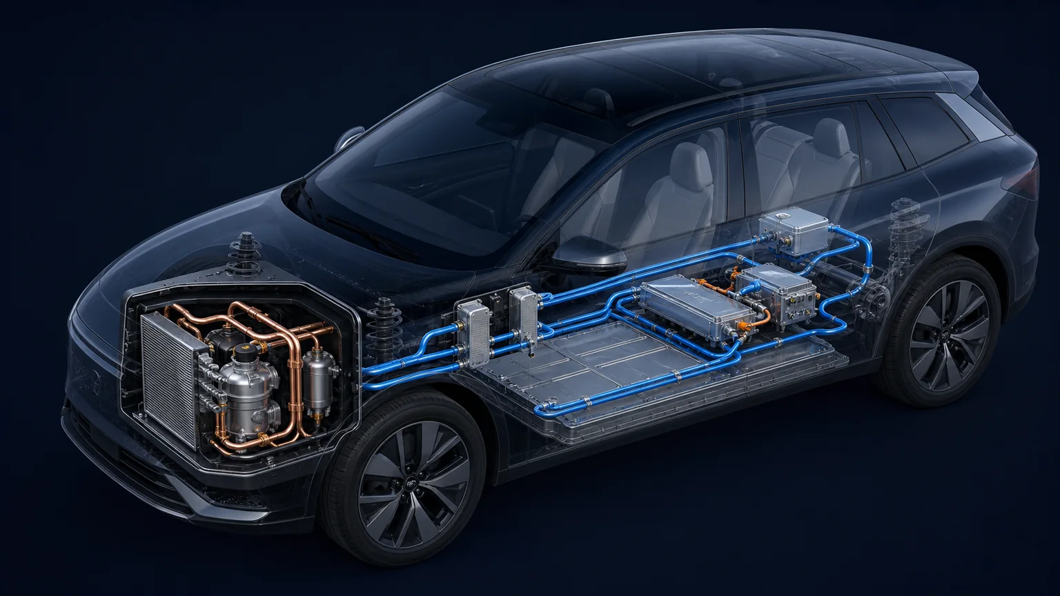
A compact R290 refrigerant loop can exchange heat with separate coolant loops for cabin and battery functions, limiting refrigerant routing through occupied areas.
Direct refrigerant and secondary-loop architectures
Direct refrigerant routing
In a direct system, refrigerant travels to heat exchangers near the thermal loads. A cabin evaporator or condenser can exchange heat directly with HVAC air, while a refrigerant chiller serves battery coolant. Direct exchange can reduce intermediate temperature differences and pumping demand, but refrigerant lines, joints and heat exchangers extend across more of the vehicle.
With a flammable refrigerant, placement and potential leak paths require detailed risk control. Component joints, crash zones, drains, ventilation and detection must be considered. The permitted charge and construction are governed by the vehicle’s design and applicable requirements.
Secondary coolant loops
An indirect system keeps the refrigerant circuit compact and transfers heat to water-glycol or another approved coolant through refrigerant-to-coolant heat exchangers. Pumped coolant then carries heating or cooling to the cabin heater core, battery plate, power electronics or external heat exchanger.
This arrangement can reduce the length of flammable-refrigerant lines and move refrigerant joints away from the cabin. It also creates additional components: coolant pumps, valves, reservoirs, sensors, degas paths and heat exchangers. Each intermediate heat exchange adds temperature approach and pumping loss, so controls and component sizing are critical.
Secondary loop does not mean inherently service-safe. R290 still exists within the sealed refrigerant module, often near high-voltage equipment. Coolant and refrigerant must remain separated inside the exchanger. A cross-leak can introduce refrigerant into a coolant circuit and potentially release it at a reservoir, vent or service point not intended for refrigerant.
Typical functional components
Electric compressor: circulates R290 and establishes pressure difference. Matching includes refrigerant compatibility, oil, displacement, speed, voltage, inverter, connector, communications, mounting, pressure envelope and safety logic.
Refrigerant-to-coolant heat exchangers: act as evaporators or condensers depending on mode. Their construction must provide pressure separation, low charge volume, acceptable pressure drop and validated cross-leak integrity.
Air-side heat exchanger: exchanges heat with ambient air. Depending on the design, it can be a refrigerant coil or a coolant radiator. A conventional automotive A/C condenser is not automatically suitable for R290 or reversible heat-pump duty.
Expansion devices and multi-way valves: route and meter flow for cooling, heating, defrost and heat-source modes. Port mapping, flow direction, coil or motor actuation and controller calibration are platform-specific.
Coolant pumps and valves: connect cabin, battery, power electronics and ambient heat exchangers. Coolant chemistry, temperature range, head/flow curve, electrical interface and diagnostic feedback matter.
Accumulator, separator and receiver functions: manage refrigerant state and help protect the compressor. Their volume, oil return and placement are part of the charge strategy.
Sensors and safety devices: pressure and temperature sensors support control; gas detection, current monitoring, insulation checks and crash signals may support safety responses. A sensor with the correct thread but wrong calibration can defeat control logic.
Leak containment is an architecture, not one detector
Containment begins with minimizing charge and joint count. Brazed or welded connections may replace serviceable joints in selected areas. Components are positioned and shielded to reduce crash or abrasion risk. Materials and seals are validated for R290, oil, temperature cycling, vibration and permeation.
Designers then consider where leaked gas could travel. Propane vapor can accumulate in poorly ventilated low areas. Drain and vent paths, cabin air inlets, enclosed modules and nearby ignition sources matter. A refrigerant detector is only one layer and must have defined placement, sensitivity, diagnostics and response.
Control responses can include shutting down the compressor, closing valves, operating fans, opening ventilation paths, limiting high-voltage functions and storing faults. The correct action depends on leak location and vehicle state. A generic aftermarket controller cannot be inserted without the platform’s safety concept.
Service containment is separate. Workshop equipment must be approved for the refrigerant and area classification. Hoses, recovery cylinders, ventilation and leak detectors must be managed so that service does not create the hazard the vehicle design sought to contain.
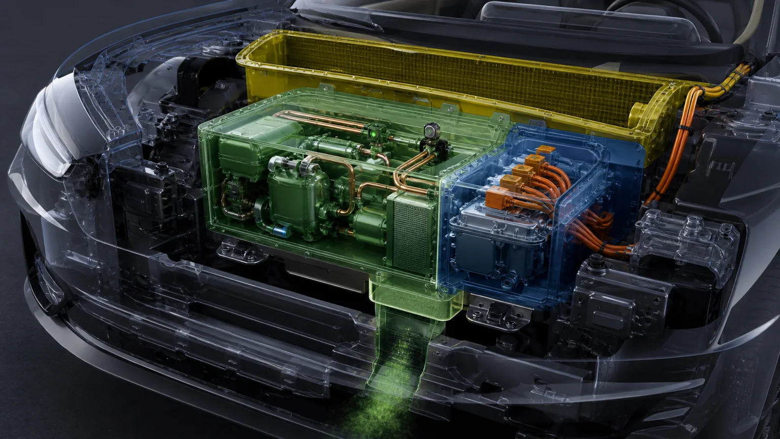
Component placement, joint reduction, gas travel paths, ventilation, detection and automatic shutdown form layered leak control around the compact circuit.
Pressure, temperature and material compatibility
R290 system pressures differ from those of R744 and cannot be inferred from R1234yf hardware. Each component must be qualified for the actual low- and high-side envelope, including hot soak, cold start, standstill pressure, control faults and pressure pulsation. Relief and containment strategies belong to the complete vehicle design.
Elastomers, desiccants, hose barriers, valve seats, motor insulation and lubricants must be compatible with refrigerant and temperature. Compatibility involves swelling, permeation, chemical stability, moisture, electrical properties and long-term cycling. A seal catalog statement that lists “propane” may not cover the vehicle’s oil and duty.
Heat exchangers must also survive cross-circuit pressure differences. In a refrigerant-to-coolant exchanger, the coolant side may remain pressurized after the refrigerant side is evacuated, or vice versa. Test procedures should address both boundaries and the consequence of internal leakage.
Oil and electric-compressor considerations
The compressor supplier specifies lubricant type and charge. Oil must lubricate bearings and compression elements, return through the circuit and remain compatible with R290, seals and motor materials. In integrated electric compressors, dielectric behavior can be important because the motor windings may contact refrigerant and oil.
Do not add universal dye or oil. A product compatible with a belt-driven hydrofluorocarbon system may change electrical insulation, viscosity or miscibility. Moisture control is critical. Keep shipping ports sealed until connection and use the service procedure for evacuation and charging.
An electric compressor contains power electronics or depends on an external inverter. Matching requires operating voltage range, peak current, communication protocol, speed command, connector, isolation monitoring and software. A nominal 400 V or 800 V label does not establish interchangeability.
Operating modes and why valve mapping matters
In cabin cooling, the refrigerant loop rejects heat to ambient and removes heat from cabin air or a cabin coolant loop. Battery cooling can share the evaporating capacity through a chiller. The controller balances cabin comfort, cell temperature, power limits and condensation protection.
In heating, the system collects heat from ambient air, power electronics, battery or another coolant source and delivers it to the cabin loop. At low ambient temperature, frost can accumulate on an air-side evaporator. Defrost temporarily changes valve routing and thermal priorities.
Battery heating can route condenser heat or heated coolant to the pack. Waste-heat recovery may connect the traction inverter and motor. Fast charging creates a strong battery-cooling demand even when cabin load is low. The same physical valve can therefore support several flow states.
Port count does not describe those states. A replacement valve must match port-to-port mapping in each actuator position, permitted flow direction, internal leakage, response time, fail-safe state, pressure range and control signal. Misrouting can send high-pressure refrigerant toward the wrong exchanger.
Same envelope can hide different plates and cross-leak margin
Multi-way valve
Port map by state, actuation, feedback, seals, pressure and fail-safe behavior
Same port count can route flow differently
Pressure/temperature sensor
Range, calibration curve, thread/seal, connector, output and diagnostics
A controller acts on the signal, not the housing shape
Coolant pump
Fluid, flow/head map, voltage, control, connector, temperature and mounting
Nominal flow does not define system operating point
Hose or line
Material/barrier, joint, pressure, permeation, routing and crash protection
Generic A/C hose may not meet R290 containment
Detector
Target gas, range, response, position, output, diagnostics and safety logic
A detector is part of a validated response chain
Serviceable boundaries may be narrow in early platforms. A manufacturer may supply a sealed thermal module rather than individual refrigerant components to preserve charge, joints and safety validation. Distributors should not promise subcomponent availability until official service information confirms it.
Incoming inspection without unsafe functional improvisation
Verify packaging, part and revision labels, shipping caps, evidence of impact, port cleanliness, connector condition, mounting geometry and supplied seals. Photograph the item before removing any cap. Maintain electrostatic and moisture controls where specified.
Do not energize an unknown compressor or valve on a bench. High voltage, uncontrolled speed and wrong commands can damage the part or injure personnel. Do not pressure-test with shop air or charge a component with R290 outside an approved facility. Functional validation needs a designed fixture, safe medium, correct controller and documented limits.
Traceability should connect the product to supplier, production lot, software/hardware revision and conformity evidence. Safety-critical changes to seals, electronics, brazing or calibration require controlled notification.
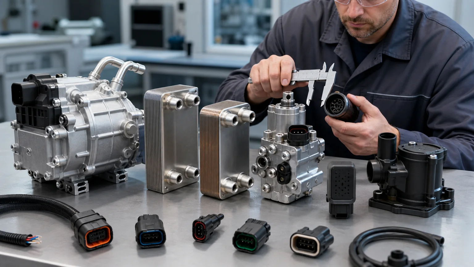
Safe matching combines OE identity, refrigerant and oil, pressure and temperature, electrical control, port mapping, leak strategy and software revision.
Diagnosis should follow the energy path
Begin with the driver or charging complaint, then identify the requested operating mode. Read thermal-control faults and live data before disturbing the circuit. Compare compressor command and speed, pressures, refrigerant and coolant temperatures, valve positions, pump speeds, fan operation and isolation or leak status.
A cabin heating complaint may originate in a coolant valve, pump, air door, sensor or control limit while the refrigerant loop is healthy. Poor battery cooling can arise from low coolant flow or an obstructed plate. Pressure alone does not reveal the complete heat path.
Use non-invasive checks first: visual inspection, connector and harness condition, coolant level and quality, diagnostic data, temperature differences and commanded actuator tests. Opening an R290 circuit is not an exploratory first step. If leak or refrigerant work is required, move to the approved facility and process.
Questions for an R290 component supplier
Which exact OE numbers, vehicle platforms and hardware/software revisions are covered?
Is the component explicitly validated for refrigerant-grade R290 and the specified oil?
What are the design and test pressure/temperature envelopes and test conditions?
What are the leakage, permeation, pulsation, vibration and corrosion requirements?
For a dual-circuit exchanger, what cross-leak and proof evidence covers both sides?
What connector, voltage, command, feedback, diagnostics and fail-safe state apply?
What seals, caps, fasteners, oil or calibration steps are included?
Can the part be replaced individually under official service information?
What workshop equipment, training and safety conditions are required?
How are part, lot and hardware/software revisions traced?
Service information, labels and logistics also define the boundary
A technician must be able to identify the refrigerant before connecting equipment. Vehicle and thermal-module labels should remain legible and should state the required service information under the applicable rules. A missing label is not an invitation to infer the charge from a later model. Confirm the VIN-specific data through the authorized information source and document any replacement label procedure.
Replacement components should arrive sealed, dry and protected from impact. Port caps preserve cleanliness but are not proof that a component contains refrigerant or oil at a particular pressure. Shipping paperwork, dangerous-goods classification, warehouse quantity limits and fire controls depend on whether an item is empty, oil-filled, refrigerant-charged or supplied as a sealed module. The supplier and carrier must classify the actual product; a buyer should not copy a classification from an empty heat exchanger to a charged assembly.
Workshops need a designated risk assessment for flammable refrigerants. It should cover ventilation, gas detection where required, ignition sources, hot work, static discharge, recovery cylinders, equipment maintenance, access control and emergency response. Because propane vapor can migrate, controlling only the space immediately above the service machine may be inadequate. Local occupational, environmental, transport and fire requirements take precedence over a generic checklist.
Recovered material must be handled through the approved refrigerant stream. Mixing refrigerants can make recovery cylinders and recycling equipment unsafe or unusable. Tools shared with other systems require a documented compatibility and contamination-control policy. A connector adapter does not make an R1234yf machine suitable for R290.
After repair, the final record should identify the component and revision, seals and fasteners used, leak-test method, evacuation and charge data, diagnostic results, safety-system check and technician authorization. This record supports future diagnosis and demonstrates that the repair preserved the designed containment layers.
System-level approval checklist
For fleet trials, track energy use, heat-up time, defrost events, battery temperature, fault history and leak-system diagnostics across seasons. Field data should be tied to software and component revisions so that an apparent hardware trend is not confused with a control update.
The exact vehicle and OE thermal architecture are identified.
Direct refrigerant and secondary coolant boundaries are mapped.
R290 charge and safety information come from authorized service data.
Component refrigerant, oil, pressure, temperature and material compatibility are verified.
High-voltage range, connectors, communications and software revisions match.
Valve port mapping and fail-safe behavior are confirmed by state.
Leak containment, detection, ventilation and control responses remain intact.
Coolant chemistry, pump/valve flow and cross-leak integrity are included.
Only trained personnel and R290-suitable equipment open the circuit.
No conversion or substitution is based solely on dimensions or refrigerant pressure similarity.
Air-side products shown in a conventional A/C condenser range and liquid-side products in an oil cooler range demonstrate familiar heat-exchanger forms, but R290 heat-pump components require platform-specific qualification. Catalog family resemblance is not approval.
Key conclusion: R290 offers a credible path to compact, efficient EV heat pumps, especially when a short refrigerant circuit works through secondary coolant loops. Its value comes with a stricter containment and service design. The aftermarket opportunity is therefore evidence-led: exact OE mapping, validated refrigerant/oil compatibility, pressure and leak integrity, correct electrical control and preservation of the vehicle’s complete safety strategy.