You are here:Home » Blog » Technical Guides » Why a Replacement Radiator Has Unused Oil Cooler Ports: Application and Fitment Checks
Why a Replacement Radiator Has Unused Oil Cooler Ports: Application and Fitment Checks
Views: 0 Author: Elecdura Publish Time: 2026-09-01 Origin: Site
A replacement radiator may have two transmission-oil-cooler fittings even when the vehicle does not use them. Many radiator families share a tank and core across manual- and automatic-transmission applications. On a correctly designed shared radiator, the internal oil cooler is a separate sealed circuit inside the radiator tank, so its unused fittings do not normally open into the engine-coolant space. That explanation must still be confirmed for the exact part number. Never assume that an unidentified opening can be left uncapped or that every extra fitting serves the same function.
The practical decision is made from the OE number, vehicle and transmission configuration, port construction, supplier application data and a visual comparison with the removed unit. Buyers selecting a wholesale automotive radiator should record these details before installation because a shared design can be correct, while a similar-looking radiator with the wrong threads, sensor provision, hose neck or mounting geometry can still be wrong.
Do not fill, bridge or improvise. Do not pour coolant into an extra fitting, connect the two oil-cooler ports together, install a random hardware plug, or apply sealant without product instructions. Identify the circuit first. Shipping caps, protective plugs, operating plugs and threaded line fittings have different functions.
Why radiator manufacturers use a shared design
A vehicle platform may be offered with several engines, manual and automatic transmissions, different trim levels, towing packages, or regional cooling specifications. Producing one radiator tank design with an integrated automatic-transmission-fluid cooler can reduce tooling and inventory complexity. The same outer radiator assembly may therefore serve a manual-transmission vehicle without cooler lines and an automatic-transmission vehicle with two cooler connections.
That consolidation can benefit the aftermarket. Distributors hold fewer part numbers, workshops gain broader coverage, and replacement availability improves for older vehicles. The tradeoff is that the installer must understand the unused features. A radiator with more ports than the removed unit is not automatically incorrect, but neither is physical fit alone enough to approve it.
MAHLE has published technical guidance explaining a case in which unused oil-cooler connections on a replacement radiator did not lead into the coolant circuit. The important lesson is structural: an integrated oil cooler is a heat exchanger contained inside a coolant tank, not a simple drilled passage that mixes the fluids. The broader lesson is caution: that construction must be supported by the exact product design and application data, not generalized to every opening on every radiator.
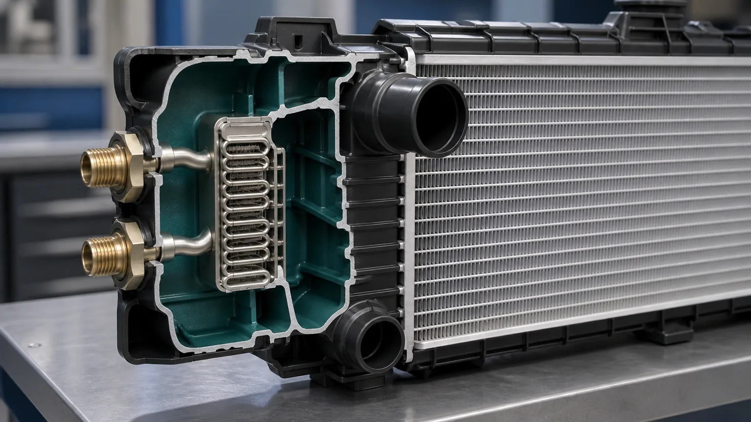
The engine-coolant tank surrounds a separate sealed ATF heat exchanger. The two fluids exchange heat through metal walls and should not mix.
How the integrated transmission oil cooler is separated
In a common arrangement, hot automatic transmission fluid enters one threaded fitting, passes through a small internal tube or stacked-plate exchanger, and exits through the second fitting. Engine coolant circulates around the outside of that exchanger within the radiator tank. Heat crosses the metal boundary, but the fluids remain in separate pressure circuits.
If the vehicle has a manual transmission and no ATF lines, nothing flows through the internal oil cooler. The unused cooler cavity can remain dry when the supplier explicitly approves that configuration. Coolant still occupies the surrounding radiator tank, and the primary radiator performs its normal engine-cooling function.
An internal breach changes the situation. A cracked or poorly sealed cooler can allow coolant and transmission fluid to mix, depending on their relative pressures. Signs may include oily contamination in the expansion tank, milky transmission fluid, changing fluid levels or transmission problems. These symptoms are not normal consequences of unused fittings and require immediate investigation.
Integrated coolers also vary. Some radiators contain an engine-oil cooler, some an ATF cooler, some both, and some only molded or machined provisions without an installed exchanger. Hybrid and heavy-duty applications may route fluids differently. The port location alone does not identify the circuit.
Shipping caps, operating caps and functional plugs are not interchangeable
A lightweight plastic cap often keeps dust, moisture and packaging debris out during transport. It may not be pressure-rated, temperature-rated or retained for vehicle service. An operating closure, by contrast, has a defined thread or retention method, sealing seat, material and environmental function. A blanking plug used in production can be another distinct part.
If the radiator instructions say the unused ATF fittings may remain open, the open state may be intentional because the internal oil circuit is dry and isolated. A protective cap might still be recommended to keep dirt out for possible future use. If instructions specify permanent caps or plugs, use the supplied or specified components. Adding a plug where none is required can damage a flare seat, split a plastic boss, introduce sealant into the cooler, or mislead the next technician.
Do not judge a cap by color. Catalog photos often show red, black or translucent plugs for shipping visibility, but color is not a universal code. Check the packing list, installation sheet, molded symbols and supplier response. Keep any removed shipping caps with the job record until fitment is verified.
A step-by-step fitment check
1. Start with the complete application identity
Collect the VIN or chassis number, make, model, production date, engine code, transmission type and code when available, market, air-conditioning configuration and towing or heavy-duty cooling option. Model-year descriptions can cross production changes. A manual/automatic dropdown may not capture a continuously variable transmission, separate auxiliary cooler or regional package.
Use the number from the removed radiator and the OE catalog, not merely a reseller stock code. Record suffixes and supersessions. A new number may legitimately consolidate several old radiators, but the catalog should show the relationship. When working from an aftermarket radiator catalog, request the cross-reference evidence for any ambiguous application.
2. Compare the complete radiator, not only height and width
Measure core height, width and thickness using a consistent convention. Compare upper and lower hose neck diameter, direction and position; filler neck or remote-tank connection; drain location; mounting pins and cushions; fan-shroud mounting points; sensor and switch provisions; overflow connection; air guides; and any oil-cooler fittings.
A radiator can drop into the support while placing a hose against a fan, changing shroud clearance or omitting a temperature switch. Conversely, a small change in tank ribbing or fin pattern may be harmless when all functional interfaces and the approved cross-reference match. Photographs should include an overall front and rear view plus close-ups of every connection.
3. Identify each extra connection
Look for a pair of similar fittings located on one tank; this pattern often suggests an internal oil cooler. Inspect whether they have external threads, internal threads, quick-connect grooves, flare seats or removable adapters. A single small threaded hole may instead be a temperature sensor or fan switch provision. A hose barb may be a vent, overflow or degas connection. Molded bosses with no drilled passage are not ports.
Do not probe deeply with metal tools. You can damage a seal, seat or thin exchanger. Use a light, mirror, clean swab at the opening only when permitted, molded part markings and product drawings. If identity remains uncertain, stop and send photos to the supplier.
4. Confirm circuit isolation
The best confirmation is manufacturer or supplier application documentation stating that the radiator includes an integrated cooler and is approved for the vehicle configuration. A drawing showing the internal circuit adds confidence. Pressure testing can verify integrity when performed with the correct fixtures, media and limits, but an uncontrolled shop-air test can be dangerous and can damage the product.
Never use mouth pressure or pour fluid into an unidentified port. If a quality team performs an incoming inspection, it should use a documented leak-test method with regulated equipment and appropriate guarding. The radiator coolant circuit and oil circuit should be tested separately according to the product specification.
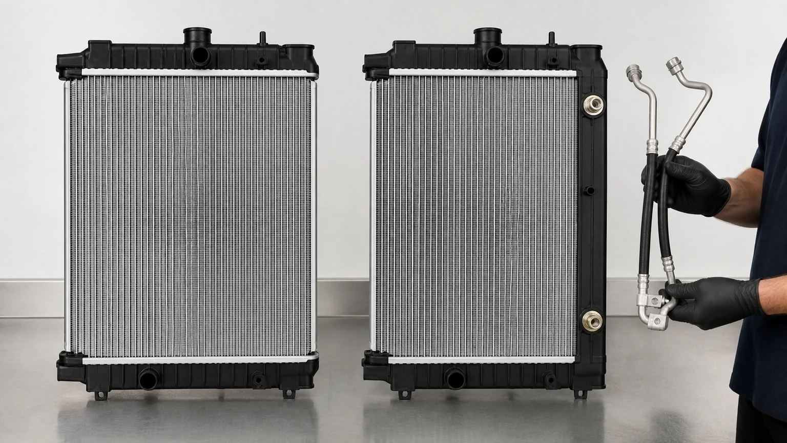
A shared radiator may use the same mounting, hose necks and core for both transmissions, while only the automatic application connects the two ATF fittings.
Manual-transmission installation
When the approved replacement is a shared manual/automatic design, the manual vehicle normally uses the engine-coolant connections only. Follow the supplier’s direction for the unused cooler fittings. Do not invent a loop hose between them. A loop can trap fluid or contamination, deteriorate, contact moving parts, and falsely suggest that the circuit serves the vehicle.
Route all engine-coolant hoses exactly as required and transfer only the specified brackets, cushions, sensor plugs and air guides. Ensure the unused fittings cannot contact the body, fan wiring or shroud. If a removable adapter projects farther than the original tank, confirm that it is meant to remain installed before removing it; the adapter may be part of the cooler seal.
After filling with the approved coolant mixture, bleed the engine-cooling circuit according to vehicle procedure. Extra ATF cooler fittings do not change the coolant bleeding path. Monitor coolant temperature, heater output, fan operation and level through the prescribed heat cycles. Recheck for leakage when cool.
Automatic-transmission installation
For an automatic application, compare fitting thread, seat and retention design with the vehicle lines. Similar thread diameters can have different pitch or sealing geometry. Some connections seal on an O-ring, some on a flare, some through a quick-connect retainer, and some use an adapter. Thread sealant on a flare or O-ring joint can prevent correct seating and contaminate the circuit.
Support the radiator fitting with the approved backup tool when tightening a line. Excess torque can rotate the fitting or damage the tank-to-cooler seal. Avoid bending a rigid line into alignment; preload can create a delayed leak. Replace clips, O-rings and seals as specified, lubricating only with an approved fluid.
After installation, set transmission-fluid level with the manufacturer’s temperature and operating procedure. Fluid lost during radiator replacement can be more than the amount visible at the disconnected ends. Verify line routing, leakage and temperature behavior during a controlled road or load test. An auxiliary transmission oil cooler may be connected in series on some vehicles, so record the original routing before disassembly.
When extra ports indicate the wrong radiator
Extra cooler ports can be acceptable, but several evidence patterns justify rejection or escalation:
The supplier cannot connect the radiator number to the vehicle or OE supersession.
The port is not part of a pair and cannot be identified from drawings or instructions.
Coolant appears at a supposed oil-cooler fitting before installation.
The required automatic-transmission line thread, seat or position differs.
A needed cooler is absent, or the replacement only has an unmachined boss.
The hose neck, filler arrangement, sensor port, drain or mounting geometry differs.
The fan shroud cannot mount without drilling, bending or loading the radiator tank.
The line or unused fitting will contact the fan, belt, body or hot exhaust component.
The packaging number and product label disagree.
There is shipping damage, bent mounting structure, cracked plastic or evidence of leakage.
A wrong-part decision should be documented before coolant is added or mounting features are modified. Photograph the labels, packaging, all ports and side-by-side comparison. This preserves return eligibility and helps the supplier correct catalog data.
Incoming inspection for distributors
Distributors can prevent repeated questions by making port configuration part of master data. A radiator record should state whether it has no oil cooler, an ATF cooler, an engine-oil cooler, or multiple coolers; the number and position of ports; fitting type; supplied adapters or caps; manual/automatic coverage; and any supersession note. Images should show both tanks and close views of the fittings.
Sampling plans should check dimensions, necks, mounting points, threads, supplied hardware, label accuracy and packaging protection. Cooler circuit integrity can be included where the supplier specification and test equipment support it. Do not publish an unverified pressure value copied from an unrelated radiator family.
Packaging matters because oil-cooler fittings can punch through cartons or be contaminated by foam fragments. Caps should remain fitted through transport when specified. A product that arrives with a loose adapter should be quarantined until the sealing arrangement is understood.
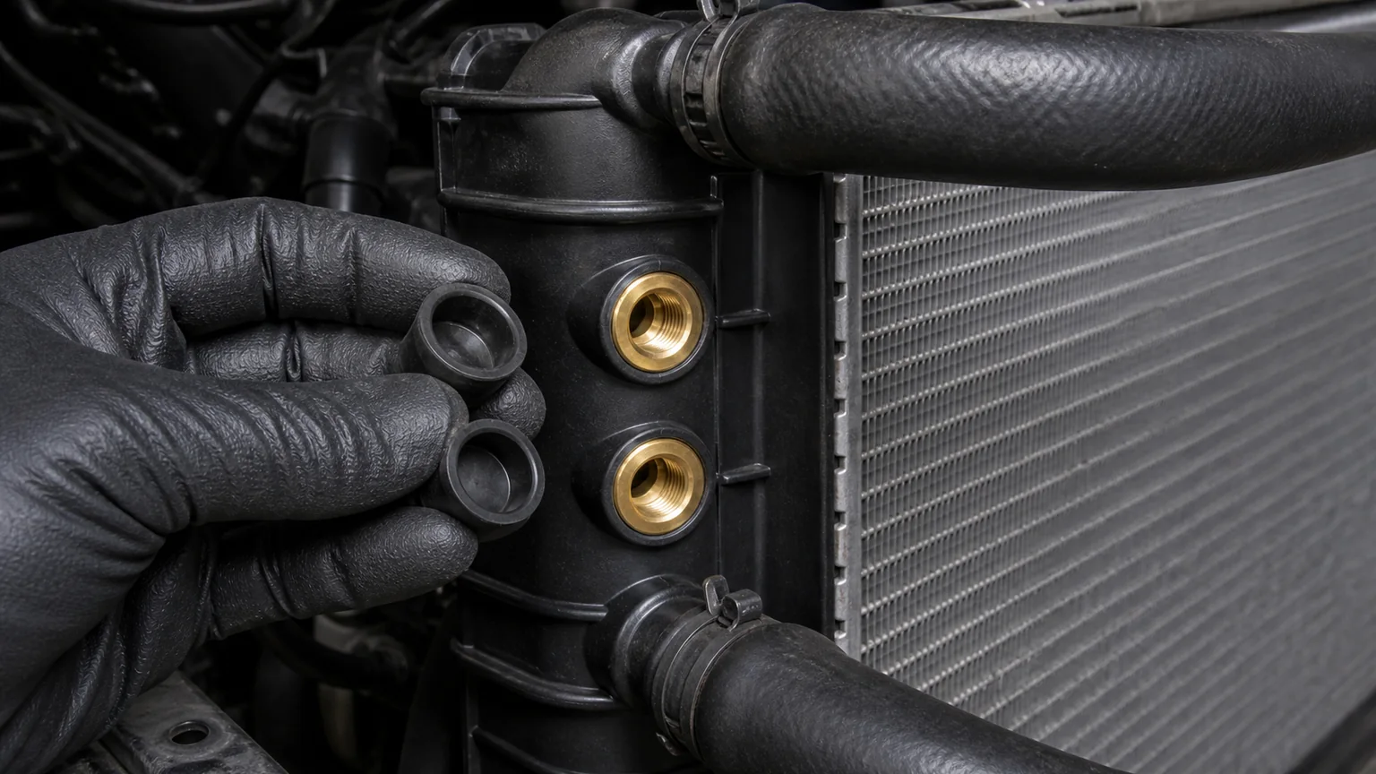
Identify whether each feature is an open oil-cooler fitting, a protected fitting, an operating plug, a sensor provision or an unmachined boss before installation.
Troubleshooting after installation
Coolant leaks near an unused fitting
Dry and clean the area, then identify the true path. Coolant may travel from a tank seam, hose neck, bleed point or upper connection and collect near a lower cooler fitting. A leak at the internal cooler attachment is possible but should be proven rather than inferred. Pressure-test the coolant circuit by the approved method and document the location.
Transmission fluid leaks at a connected fitting
Stop and inspect the line seat, O-ring or retainer, adapter torque, thread damage and line alignment. Confirm that the fitting did not rotate in the tank. Do not repeatedly tighten beyond specification. A deformed flare or cut O-ring requires correction, not more force.
Coolant and transmission fluid appear mixed
Do not operate the vehicle. Confirm the fluids and consider other possible heat exchangers, then test the relevant circuits. Transmission friction materials and cooling-system elastomers can be damaged by cross-contamination. Follow vehicle-maker procedures for component replacement and cleaning; a quick drain-and-refill may not remove contaminated fluid from the torque converter, valve body, heater core or hoses.
The engine overheats even though the radiator fits
Check air bleeding, thermostat operation, pump flow, fan rotation and command, shroud sealing, air guides, coolant mixture, cap function and external obstruction. Compare core specification and fin condition. The existence of dry unused oil-cooler ports does not normally reduce coolant circulation, so avoid treating them as the cause without evidence.
Fitment evidence to include in an RFQ
Field
Useful buyer detail
Vehicle
VIN/chassis, make, model, production date, market and engine code
Transmission
Manual, automatic, CVT or other type; transmission code when available
Numbers
OE radiator number, removed-unit label and any known supersession
Core
Measured height, width and thickness with stated convention
Connections
Hose necks, filler/expansion arrangement, oil-cooler ports, sensors and drain
Fittings
Thread or quick-connect type, sealing seat, adapter and line photos
Mounting
Pins, cushions, brackets and fan-shroud points
Commercial
Required quantity, destination, packaging and labeling needs
Vehicle-specific ranges such as an aftermarket Fiat radiator collection still require OE and configuration confirmation because one model family can contain several cooling packages. A complete RFQ reduces the chance that a shared design is rejected unnecessarily or that a genuinely incompatible unit is installed.
Final decision checklist
One final check is to compare the installed radiator from the same camera angles used before removal. Confirm that hoses retain natural curves, clips sit in their original zones, wiring is not stretched, and the fan turns freely with the specified static clearance. Then mark the job record with the disposition of each unused feature—for example, “integrated ATF cooler ports intentionally unused on manual transmission; supplier application confirmed.” That short statement is valuable when another technician services the vehicle months later and wonders whether a connection was forgotten.
The exact replacement number is linked to the vehicle and OE reference.
Transmission and cooling-package configuration are confirmed.
Every extra opening has been positively identified.
Supplier information confirms whether unused cooler fittings remain open, capped or plugged.
Oil-cooler and coolant circuits are structurally separate for this design.
All hose necks, fittings, sensors, mounts and shroud points match.
Automatic-transmission fittings have the correct thread, seat, seals and routing.
No shipping plug is being mistaken for a permanent pressure closure.
Coolant and transmission circuits will be filled, bled and checked by their own procedures.
Photos and measurements are saved before modification or installation.
Key conclusion: unused radiator oil-cooler ports are often a normal result of a consolidated manual/automatic radiator design, not a path for coolant to escape. Approval depends on exact application data and positive port identification. If the circuit, fitting or closure requirement is unclear, pause the installation and obtain a drawing or written supplier confirmation.