You are here:Home » Resources » Blog » Industry Insights » 12V/24V vs 48V Brushless Cooling Fans: Power, Connectors, LIN/PWM, and Application Matching
12V/24V vs 48V Brushless Cooling Fans: Power, Connectors, LIN/PWM, and Application Matching
Views: 0 Author: Elecdura Publish Time: 2026-08-31 Origin: Site
A 12 V, 24 V, or 48 V brushless cooling fan cannot be matched by diameter and voltage alone. The replacement must also agree with continuous and peak power, connector keying and pinout, PWM or LIN command, speed or fault feedback, rotation, airflow direction, blade and shroud geometry, mounting points, controller integration, and the vehicle’s fail-safe strategy. Applying battery power to an unknown communication-controlled fan can damage its electronics. The safest buying process starts with the OE number, label, full connector photographs, installed orientation, dimensions, and application data.
Brushless fans are increasingly used because electronic commutation enables efficient variable-speed control, diagnostic feedback, compact packaging, and high power density. The same electronics that create those benefits also make visual substitutions risky. Elecdura’s guide to brushless and brushed radiator fan motors explains the basic motor difference. This guide addresses the next purchasing question: what changes when nominal system voltage and communication are part of the fan assembly.
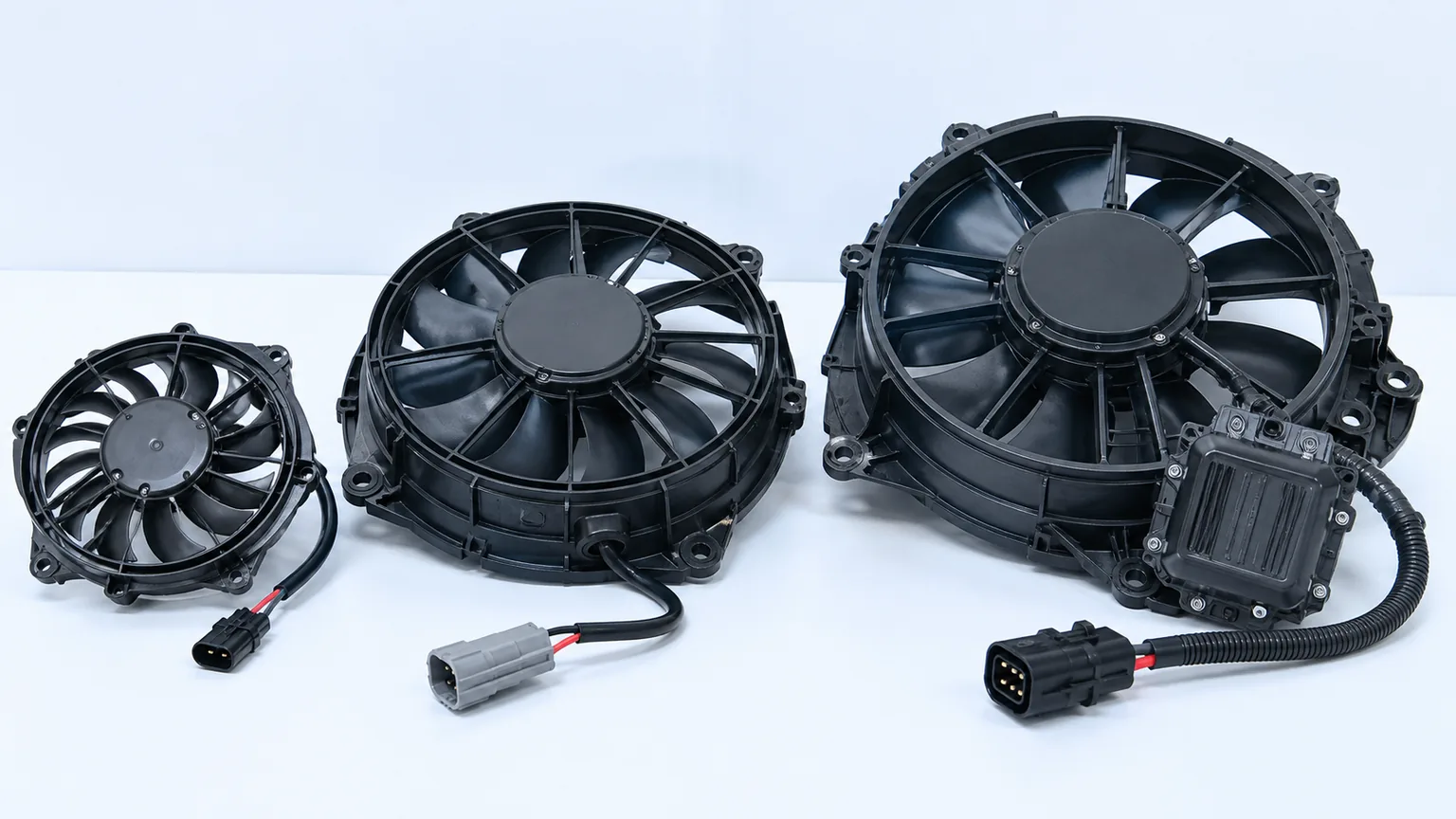
Fans with similar diameters can have different voltage, power, control, rotation, and mechanical interfaces.
The nine fields that decide compatibility
Field
What to verify
Why a mismatch matters
Nominal voltage
12 V, 24 V, 48 V or a documented range
Wrong voltage can prevent operation, trigger protection, overheat electronics, or cause immediate damage.
Power/current
Continuous and peak input, inrush behavior, fuse and wiring capacity
A fan may fit but exceed the harness, relay, controller, or DC/DC converter capacity.
Command
Direct power, switched stages, PWM, LIN, CAN or another documented interface
A fan that never receives a valid command may remain off or enter a fail-safe speed.
Feedback
Tachometer, diagnostic/status line, current feedback or network message
The vehicle can set faults or derate even if the fan physically spins.
Connector/pinout
Key, latch, pin count, terminal size, wire position and sealing
Similar plugs may carry different power, ground, wake, command and feedback assignments.
Rotation
Clockwise/counterclockwise viewed from a defined side
Wrong rotation reduces airflow and can loosen hardware or load the blade incorrectly.
Airflow direction
Puller/pusher and flow through the installed cooler stack
A backward fan can recirculate hot air or oppose road airflow.
Mechanical fit
Fan diameter, depth, shroud, mounts, blade clearance and stack position
Contact, leakage around the shroud, vibration, or poor coverage can destroy performance.
Environmental rating
Temperature, water/dust exposure, vibration, salt/corrosion and duty cycle
Electronics and bearings may fail even when initial bench operation looks correct.
Voltage changes current, wiring, and system architecture
Electrical input power is approximately voltage multiplied by current. For the same ideal input power, raising voltage reduces current. A 1.2 kW load would theoretically draw about 100 A at 12 V, 50 A at 24 V, or 25 A at 48 V before accounting for efficiency and operating variation. That simplified calculation explains why higher voltage is attractive for high-power fans: lower current can reduce conductor size and distribution losses. It does not mean the three fans are interchangeable through a voltage converter.
Actual fan current changes with speed, static pressure, air density, control strategy, motor efficiency, and temperature. Start-up behavior can also differ because brushless electronics may ramp the motor rather than create the inrush pattern of a brushed DC motor. A supplier should provide the rated operating range, maximum or peak current where relevant, input power under stated conditions, and the fan performance curve—not just a nominal voltage on the carton.
A 48 V vehicle may still contain 12 V loads supplied by a DC/DC converter, and a 12 V vehicle can contain an isolated higher-voltage thermal device. Never infer the fan voltage from the main battery architecture. Read the fan label and OE data. Likewise, do not connect a 48 V fan directly to the traction battery; automotive “48 V” and high-voltage traction systems are different electrical domains with different safety and isolation requirements.
Why 48 V is appearing in thermal management
Vehicle makers use 48 V architectures to support higher electrical loads with manageable current. Cooling demand is growing as vehicles add electrified powertrains, advanced charging, emissions equipment, dense underhood packaging, and more controlled thermal circuits. A high-power fan can be one of several 48 V loads alongside pumps, compressors, heaters, steering, or chassis systems.
For the aftermarket, the important change is that a fan may be part of a coordinated power and software architecture. The vehicle controller can command speed according to coolant, refrigerant, battery, inverter, ambient, vehicle-speed, and fault inputs. The fan’s internal electronics may report speed, temperature, overload, blocked-rotor, or communication status. Substituting a generic fan can remove those functions even if it moves air on a bench.
PWM and LIN are not interchangeable words
Pulse-width modulation (PWM) is commonly used as a speed command, but the electrical details matter: frequency, duty-cycle interpretation, voltage level, pull-up or open-collector arrangement, active-high/active-low behavior, and fail-safe response can differ. A fan may treat a missing signal as off, a fixed emergency speed, or a fault. Measuring only “there is a square wave” does not prove the command is correct.
LIN is a serial communication network. A LIN-controlled fan can require a valid wake-up condition, schedule, message identifier, checksum/version, command encoding, and diagnostic exchange. Supplying power and ground without valid communication may produce no movement or a designed fail-safe mode. Wire count cannot prove a fan is LIN. A three- or four-pin connector can be assigned in many ways.
Some applications use CAN or a dedicated proprietary interface, while others place the control electronics in a separate module. Always use the vehicle wiring diagram, fan manufacturer data, or a verified OE cross-reference. Elecdura’s PWM and LIN cooling-fan test guide explains why command, supply, ground, and feedback must be evaluated together.
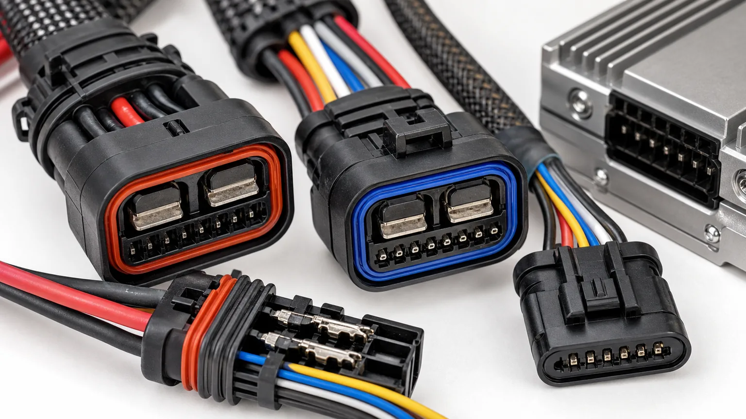
Pin count is only a clue; the documented pinout and protocol determine the electrical interface.
Connector inspection needs two views
A useful connector photograph shows both the terminal face and the wire side. The terminal face records cavity count, keying, guides, seal, latch, and terminal size. The wire side shows which cavities are populated, wire colors and gauges, strain relief, and whether a separate shield or wake line is present. Include a wider image that establishes orientation on the fan.
Do not rely on wire color across suppliers. Do not force a plug because the latch is close. A small keying difference can intentionally prevent the wrong voltage or control type from being connected. If an adapter harness is offered, it needs a documented electrical function—not merely wires between two plug shells.
High-current terminals deserve particular attention. Heat discoloration, relaxed contact force, corrosion, fretting, water tracks, or a melted cavity can increase voltage drop and create intermittent fan faults. Replacing the fan without repairing the connector may damage the new unit. Conversely, a connector fault should not be used to justify a fan warranty claim without load-test evidence.
Rotation and airflow direction are different checks
“Clockwise” is ambiguous unless the viewing side is stated. A supplier drawing may define rotation viewed from the motor side, blade side, or shaft end. Photograph or copy the arrow and its reference. If no reliable marking exists, confirm through application data or a controlled test.
A fan’s job is to move air through the intended cooler stack. A puller is normally mounted behind a radiator or condenser and draws air through it; a pusher is normally mounted ahead and forces air through. Blade sweep, airfoil section, motor rotation, shroud, and installation side work together. Reversing polarity on a brushed motor may change rotation, but many brushless fans will not reverse through polarity and may be damaged by incorrect connection.
A fan can spin and still move very little useful air if the blade is wrong for the rotation, the shroud is missing, the gap around the core is open, or the assembly is installed on the wrong side. The existing Elecdura guide to a radiator fan spinning backward after replacement provides a diagnostic sequence for that symptom.
Static pressure matters more than free-air appearance
A cooling fan works against the restriction of the grille, condenser, radiator, charge-air cooler, oil cooler, screens, guards, and contamination. Free-air airflow measured with no resistance does not predict performance in the installed stack. The supplier should provide a fan curve showing airflow across a useful static-pressure range at a stated voltage, speed, and air condition.
Shroud geometry determines how much of the core the fan actually uses and how much air recirculates around the blade. A smaller high-speed fan may produce a strong local stream but leave much of the core inactive. A large blade with poor tip clearance or an open shroud can also underperform. For a replacement assembly, compare the full shroud, sealing edges, flaps, rings, and mounting relationship—not only blade diameter.
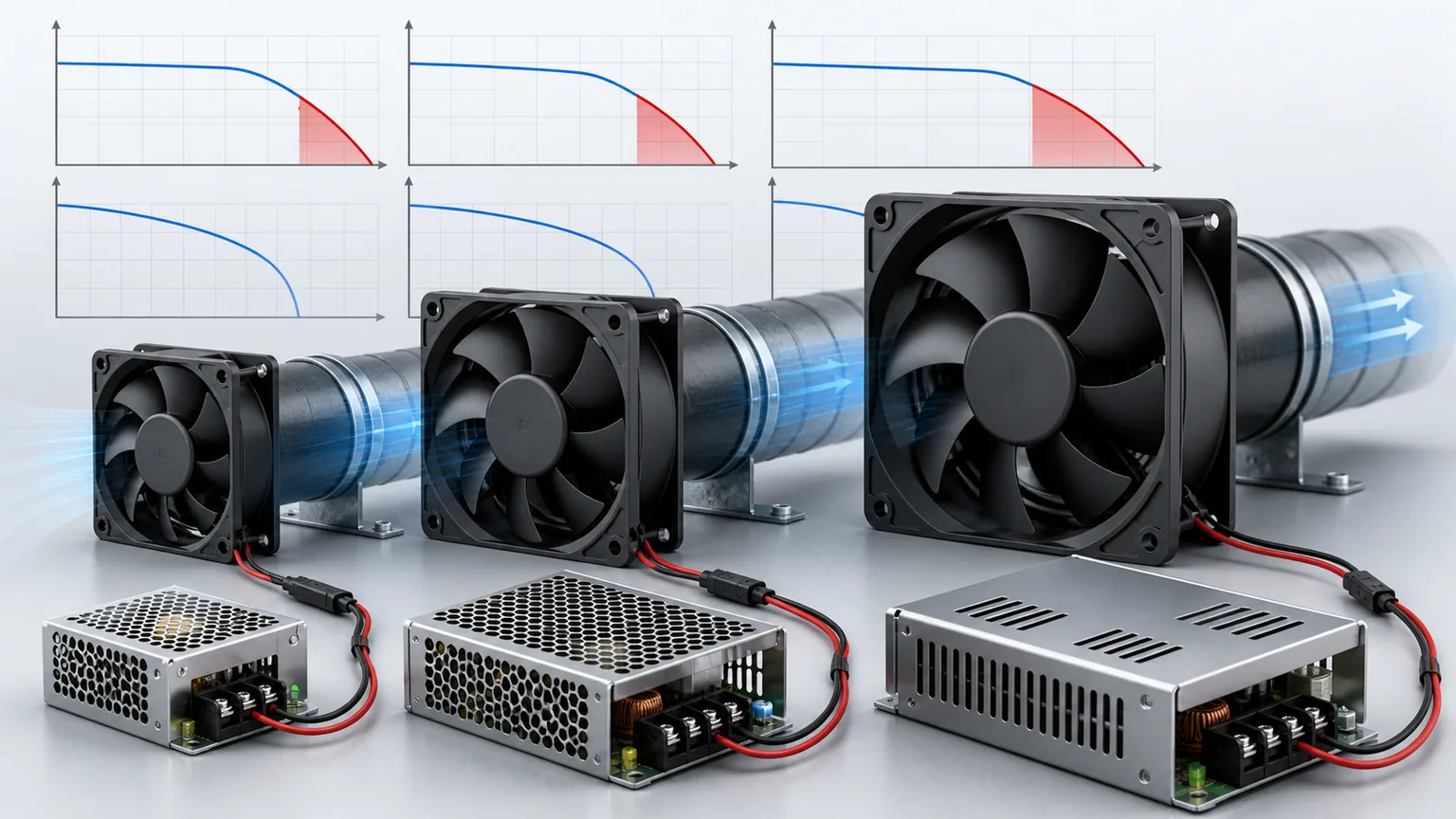
Electrical input and airflow must be evaluated at the restriction and operating condition the vehicle actually creates.
Safe bench validation
A bench test should be performed only with a documented pinout, command method, current limit, guarding, and secure fixture. Large vehicle fans can accelerate quickly, draw high current, ingest loose objects, and produce dangerous blade energy. Do not hold a fan by hand or place it loose on a bench.
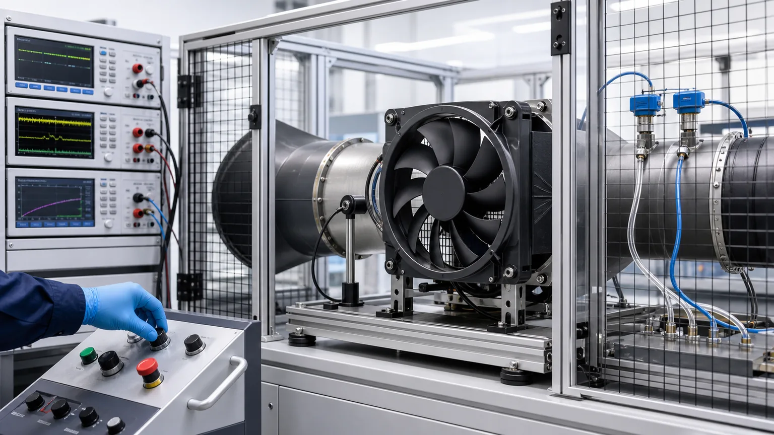
A controlled station may include an appropriately rated isolated supply, fuse or breaker, emergency disconnect, current measurement, command generator or network interface approved for the fan, tachometer, airflow or pressure instrumentation, temperature monitoring, and a guard that prevents contact or debris ingestion. The operator should stand clear of the blade plane and follow the part’s service instructions.
Measure supply voltage at the fan under load, not only at the power supply. Record current and speed at defined commands after stabilization. If testing airflow, control the duct or test geometry so samples can be compared. Note ambient temperature and whether the fan electronics reduce power as temperature rises. A short no-load spin does not validate high-static-pressure thermal duty.
Do not probe unknown communication pins with test power. Do not use a generic PWM generator until frequency, level, grounding, and fail-safe behavior are known. For vehicle diagnosis, compare commanded and actual speed, load-test power and ground, and inspect network data according to service information.
Thermal derating and protection behavior
Brushless fan electronics can monitor current, motor position, temperature, and rotor condition. Protection strategies may limit current, reduce speed, retry after a blockage, shut down until power is cycled, or report a fault. What looks like a weak fan can therefore be a controlled response to high electronics temperature, low supply voltage, blocked airflow, mechanical drag, or invalid communication.
A substitute fan with a different protection curve may operate normally in a cool workshop and derate in a hot vehicle. Ask for operating-temperature range, derating information, blocked-rotor protection, water/dust rating where stated, vibration validation, and any diagnostic behavior relevant to the application. Avoid translating a generic IP rating into a guarantee for pressure washing, immersion, salt spray, or a specific connector orientation unless the test scope supports it.
Fitment evidence for a replacement fan
Identity
vehicle/equipment model, VIN or serial range, engine or drive version, production date;
complete fan assembly OE number and all suffixes;
motor/controller manufacturer number, voltage and power label;
serial, batch, barcode, or hardware revision.
Electrical
nominal voltage and documented operating range;
connector terminal and wire-side photographs;
pinout, control protocol and required command;
fuse, wiring, controller, and expected feedback;
fault code and measured voltage drop under commanded load.
Mechanical and airflow
complete shroud width, height, depth, and mounting datums;
fan diameter, blade count, blade shape, motor position and tip clearance;
rotation stated from a defined viewing side;
puller/pusher role and airflow arrow;
cooler-stack layout and obstructions;
performance requirement or approved OE interchange.
These fields also help determine whether the buyer needs a complete assembly or only a motor. Elecdura’s radiator fan motor versus complete assembly guide explains the mechanical and control risks of partial replacement.
Incoming quality checks for a distributor
Begin with a verified golden sample and controlled drawing. Compare the box and unit labels, voltage, connector, terminals, harness routing, grommets, controller potting, motor attachment, blade part number, rotation mark, shroud profile, mounts, flaps, clips, and supplied hardware. Look for blade distortion, hub cracks, rub marks, foreign material, loose fasteners, bent shrouds, or impact transmitted through the motor.
A sampling test can record no-command behavior, staged command response, speed, current, vibration, noise, and diagnostic feedback where a safe documented interface exists. For a new supplier, performance testing against static pressure is more meaningful than a free-air spin. Define acceptance limits, warm-up, ambient condition, fixture, sensor calibration, and sample plan before the order.
A safe repeatable bench compares command, electrical input, mechanical behavior, and airflow under controlled restriction.
Common misdiagnoses and ordering errors
“The plug fits, so the fan fits.” Pinout, voltage, protocol, power, and feedback may differ.
“It is a 48 V vehicle, so the fan is 48 V.” The vehicle can contain multiple electrical domains.
“Three wires means PWM.” A third wire can be command, feedback, wake, diagnostic, or network.
“The fan spun on the bench.” A free-air spin does not prove installed airflow, communication, diagnostics, or hot-duty durability.
“Higher wattage is an upgrade.” The harness, controller, fuse, mount, shroud, noise, and cooler stack may not support it.
“Brushless fans reverse with polarity.” Integrated electronics normally require correct polarity and may be damaged.
“Clockwise matches clockwise.” The viewing side must be defined.
“The fan is bad because it is not at full speed.” The system may be commanding a lower speed or the fan may be protecting itself.
RFQ checklist
Category
Required information
Application
VIN/equipment serial, model, production date, engine/drive and market
OE identity
Complete assembly and motor/controller numbers, suffixes, label and barcode photos
Electrical
Nominal range, rated power/current, connector both sides, pinout, fuse/wire and controller
Control
PWM/LIN/CAN/direct/staged command, signal definition, feedback and fail-safe behavior
Mechanical
Shroud dimensions, mounting datums, depth, fan diameter, blade count, clearances
Airflow
Rotation with viewing side, pusher/puller, airflow arrow, required curve or OE interchange
Environment
Ambient range, water/dust/salt exposure, vibration and duty cycle
Validation
Golden sample, test points, current/speed/airflow limits, lot sampling and records
Commercial
Quantity, destination, packaging, documentation and schedule
Frequently asked questions
Can a 24 V fan run on 12 V at lower speed?
Do not assume so. Its electronics may not start, may enter undervoltage protection, may communicate incorrectly, or may operate outside validated cooling performance. Use only the documented voltage range and application.
Can a 48 V fan replace two 12 V fans?
Not as a simple parts substitution. Power supply, controller, communication, airflow distribution, shroud coverage, redundancy, diagnostics, mounting, and fail-safe operation would all need engineering validation.
How can I tell whether a fan uses LIN or PWM?
Use the vehicle wiring diagram, OE service information, fan manufacturer data, or a verified cross-reference. Connector and wire count alone are not reliable.
Does lower current mean a 48 V fan uses less power?
Not necessarily. Higher voltage can deliver the same power at lower current. Compare actual input power, airflow at static pressure, duty cycle, and efficiency under the same operating condition.
What should be included in a warranty claim?
Include application and OE identity, serial/lot, connector and installation photos, commanded versus actual speed, voltage at the fan under load, ground drop, current, fault codes, control-signal or network evidence, blade/shroud condition, obstruction/rub evidence, and the returned unit protected from further damage.
Match the complete electrical-airflow system
The move from 12 V to 24 V and 48 V fans is not only a change in label voltage. It changes current, power distribution, electronics, communication, diagnostics, and the way a fan participates in vehicle thermal control. The correct replacement must satisfy the complete interface: electrical supply, command and feedback, connector and pinout, rotation and airflow, shroud and mounting, performance under restriction, protection strategy, and environmental duty.
For a fitment review, send Elecdura the vehicle or equipment application, OE and manufacturer labels, voltage, connector terminal and wire-side photographs, pin count and control information, shroud and mounting dimensions, fan diameter and rotation, installed cooler-stack photographs, measured fault evidence, quantity, and destination. Those details allow a verified match instead of a risky diameter-and-voltage guess.