English
Views: 0 Author: Elecdura Publish Time: 2026-08-13 Origin: Site
Replace only the radiator fan motor when testing isolates an electrical or mechanical failure inside the motor, the blade and shroud are undamaged, the controller or resistor remains serviceable, the connector and harness are sound, and an application-specific motor is supplied as a service part. Replace the complete fan assembly when damage affects more than the motor, the electronics are integrated or not serviced separately, the blade or shroud is cracked or distorted, bearing failure has allowed contact, corrosion or heat has damaged connectors, or the vehicle manufacturer specifies a complete module.
That answer depends on diagnosis and fitment, not on which part is cheaper. A motor-only repair can save money and material when the rest of the assembly is healthy. It becomes false economy when an old blade, worn connector, failed control module, or misaligned shroud remains in service. Buyers can compare Elecdura's application-specific radiator fan motors with complete cooling fan assemblies after the failed elements and OE configuration have been identified.
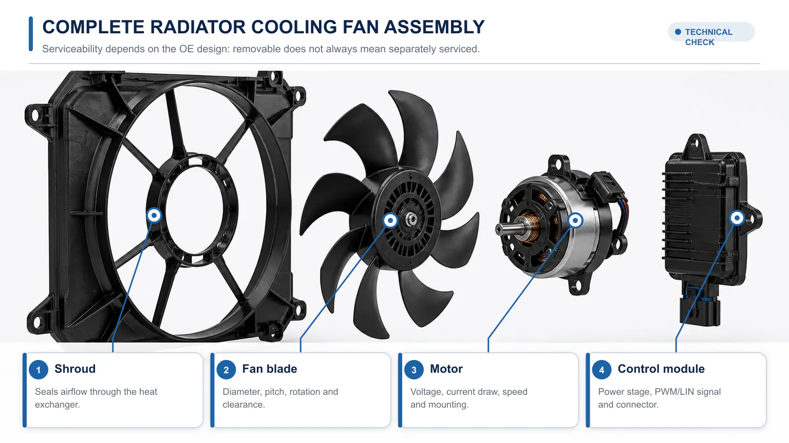
A complete cooling fan assembly can include the shroud, blade, motor and electronic control module.
Inspection or test result | Motor only may be appropriate | Complete assembly is usually safer |
|---|---|---|
Motor does not run with verified power, ground, and command | Yes, if motor is separately serviceable | Yes, if motor/controller is integrated |
Blade cracked, warped, loose, or rubbed the shroud | No | Yes |
Shroud cracked, distorted, or mounts broken | No | Yes |
External module/resistor has failed | Keep motor only if it passes load testing | Use assembly if module is integral or other damage exists |
Connector overheated or terminals lost tension | Only with approved harness/connector repair and sound components | Often, especially when pigtail/module damage is widespread |
High current draw with stiff or noisy bearings | Possible if blade/shroud/controller are verified | Prefer assembly if heat or contact damaged other parts |
Vehicle service information requires a dual-fan module | No | Yes |
Fitment or control type is uncertain | Do not order yet | Do not order yet |
A complete cooling fan assembly may include one or two motors, blades, a molded shroud, mounting points, wiring, connectors, a resistor, relay, or electronic control module. Some modern brushless fans integrate power electronics into the motor. Other vehicles use a replaceable module attached to the shroud. Older systems may use simple relays and fixed resistors elsewhere in the vehicle.
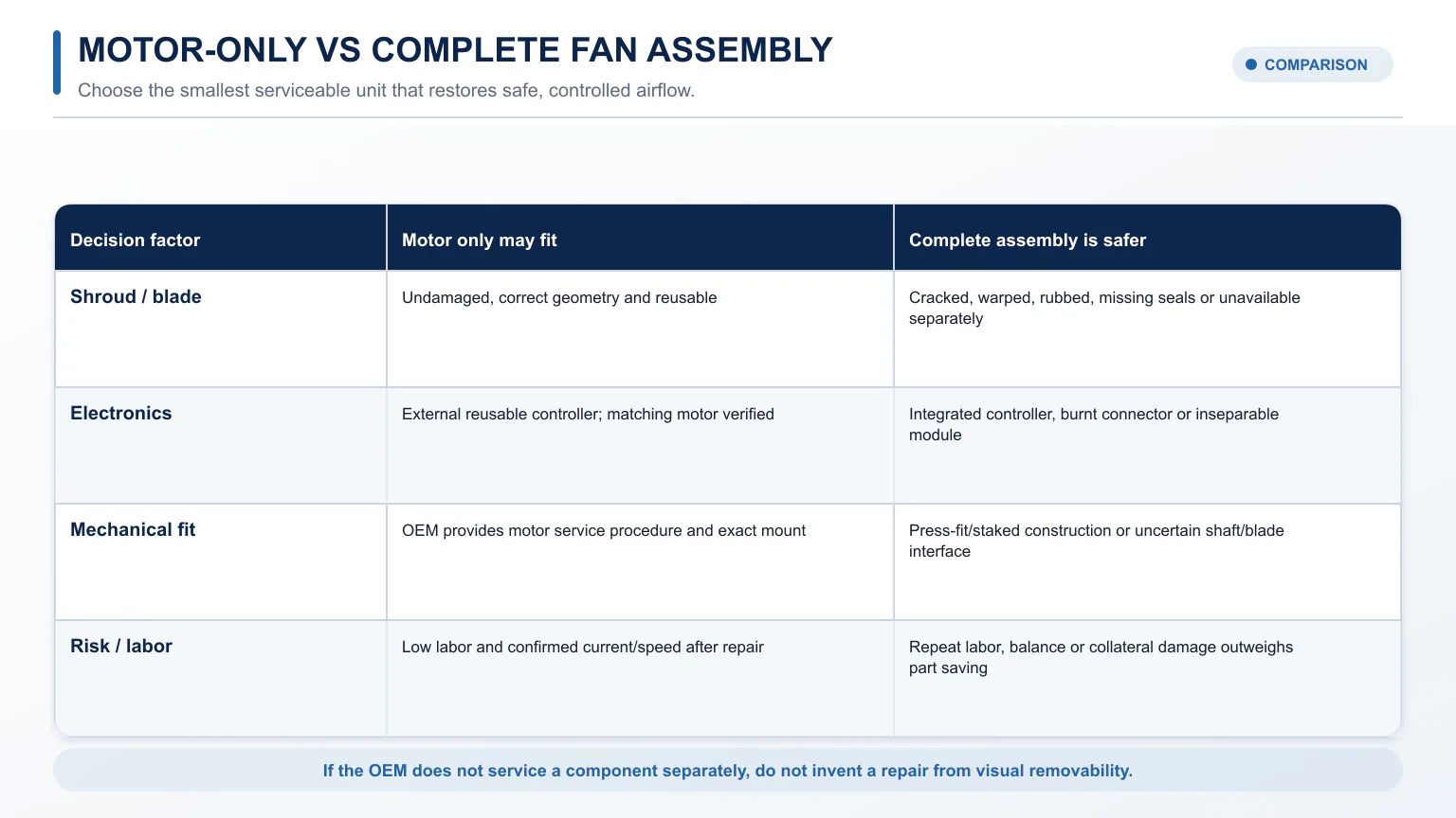
This architecture determines what can be serviced. A motor being physically removable does not prove the OEM or aftermarket supports it separately. Installing a universal motor can change blade speed, direction, current draw, airflow, noise, and controller loading. Conversely, a replaceable module should not force replacement of two healthy motors when an application-specific module is available and the rest of the assembly passes inspection.
Start by identifying every component in the original assembly and locating the vehicle-specific wiring diagram and service procedure. Elecdura's fan control module category illustrates why the controller must be considered separately from the motor even when both are sold for the same cooling system.
Follow the fan command from sensor input to measured airflow before replacing a component.
A non-operating fan does not automatically mean a failed motor. HELLA's cooling-system diagnostic guidance tells technicians to check the fan switch-on point, fuse, thermal switch or temperature input, fan control unit, mechanical damage, and airflow restrictions. A useful diagnostic sequence follows the command from the control system to the airflow result.
Record coolant temperature, A/C request, high-side pressure if relevant, vehicle speed, ambient temperature, and when the problem occurs. A fan may be commanded only at a threshold or at a variable speed. “It did not run with a cold engine” is not proof of failure. Overheating at highway speed may point to coolant flow, combustion, or radiator restriction rather than an electric fan that is most important at low road speed.
Read all relevant modules, not only the engine ECU. Record coolant-temperature plausibility, A/C pressure, fan command percentage, requested and actual speed where available, and network faults. A fan-related DTC identifies a monitored circuit or performance problem; it does not prove the motor is defective. Sensor, wiring, ECU, module, or mechanical faults can set similar codes.
Command low, medium, and high fan speeds while observing current, voltage, speed feedback, noise, vibration, and airflow. Keep hands, clothing, leads, and tools away: an electric fan can start without warning even when the engine is stopped. Never energize an unrestrained motor or blade on a bench.
A digital meter may show battery voltage through a corroded connection when no current flows. Measure voltage drop while the fan is commanded. Test the positive path from battery or power distribution to the fan and the ground path from fan to battery negative. Follow the manufacturer's limits. Also inspect high-current fuses, relays, splice points, grounds, and terminals for heat, corrosion, or loss of contact tension.
Depending on architecture, the motor or module may receive a relay-switched feed, resistor stages, a pulse-width-modulated command, or LIN communication. Use the specified test method and oscilloscope where required. Do not apply battery voltage to an unknown communication or control pin. A good power and ground supply with no valid command indicates an upstream control problem; a valid command with no output narrows the problem to the module, motor, or mechanical load.
With the system safely disabled, inspect blade cracks, missing weights, hub looseness, shroud rubbing, foreign objects, bearing roughness, water entry, distorted mounts, and blocked heat exchangers. Check that the blade is the correct design and rotation. A fan spinning in the wrong direction may appear functional but move little air through the radiator stack.
The repair decision changes with shroud and blade condition, electronics, serviceability and comeback risk.
A motor-only repair is strongest when all of the following are true:
Power, ground, command, sensors, fuses, relays, wiring, and upstream controls have been verified.
The motor is open, shorted, seized, noisy, slow, or drawing abnormal current under the vehicle-specific test.
The blade is undamaged, balanced, tight on the hub, and compatible with the replacement shaft/hub.
The shroud is rigid, correctly sealed to the heat-exchanger area, and has intact mounts.
The resistor or electronic controller passes testing or is separately replaced.
Connectors and terminals show no heat damage, corrosion, or loss of tension.
The manufacturer or a qualified aftermarket catalogue lists a motor for the exact application.
Installation does not require destructive blade removal or reuse of a compromised retention feature.
Motor-only replacement is common where the assembly was designed for service and the surrounding components are relatively new. It can also be practical for commercial fleets that inspect and stock each subcomponent. Document current draw and airflow after repair so a saving today does not become an overheating comeback.
Choose the complete assembly when the fan is an integrated system or when one failure has damaged related parts. Strong reasons include:
An integrated brushless controller/motor that is not serviced separately.
A vehicle-specific bulletin or parts catalogue that supplies only the complete fan module.
Cracked blades, a loose hub, missing balance material, or contact with the shroud.
Broken shroud mounts, warped plastic, missing sealing flaps, or poor radiator coverage.
Dual fans with heat-damaged shared wiring or a failed integrated control unit.
Water intrusion, corrosion, overheated connectors, or melted harness sections.
High mileage and multiple marginal components where subcomponent labor approaches assembly cost.
Previous incorrect repairs, mixed blades/motors, or unknown application parts.
A HELLA application bulletin for certain Porsche Cayenne vehicles, for example, describes contamination-related failure in a dual fan module and states that the complete module is replaced according to the vehicle manufacturer. That example demonstrates why vehicle-specific information controls the repair; it does not mean every dual fan requires a complete assembly.
The VIN and OE number are the starting point. Then compare the physical and electrical configuration:
Fan count and diameter: single/dual configuration and blade envelope.
Blade design: blade count, pitch, hub, rotation, and puller/pusher airflow.
Motor rating: 12 or 24 V, wattage, current, speed, and duty.
Control architecture: relay/resistor, PWM, LIN, integrated brushless electronics, or external module.
Connector: keying, pin count, terminal size, wire gauge, and pin function.
Feedback: speed or diagnostic output expected by the ECU.
Shroud: radiator/condenser coverage, air flaps, ducting, and sealing foam.
Mounting: tab positions, isolators, screw/clip type, and hose or harness clearances.
Two assemblies may plug in and bolt up yet have different wattage or control calibration. That can create low airflow, electrical overload, a fan code, excess noise, or continuous operation. Send the supplier the VIN, OE number, connector photo, full assembly photo, dimensions, and any module label.
Compare more than parts price. A motor-only repair includes diagnosis, assembly removal, blade and motor transfer, fasteners or retention components, wiring, and validation. A complete assembly may cost more but arrive balanced, shrouded, wired, and controlled as one application-specific unit. It can reduce labor and uncertainty.
Use a simple expected-cost model: part cost + labor + downtime + probability of a repeat repair × repeat-repair cost. A $70 motor is not cheaper than a $220 assembly if a brittle blade fails, a worn connector overheats, or the reused module stops controlling speed. The reverse is also true: replacing a $500 assembly when a $90 external module is the only proven fault wastes money.
Water can travel through a cracked module case, an unsealed connector, or capillary action inside wiring. Green or black terminals, swollen seals, and moisture tracks require more than replacing the component named by a fault code. Inspect the mating connector and harness far enough to find clean copper. A new motor connected to high-resistance terminals will run slowly, draw abnormal current, generate heat, and may damage a new module.
A worn motor bearing can let the blade move axially or radially until it contacts the shroud. If the motor is replaced but a scraped, cracked, or distorted blade is reused, imbalance can shorten new bearing life and create noise. Check the shroud for heat deformation and verify clearance at every blade position. Do not bend plastic blades back into shape or mix blades between unverified motors.
A repeatedly blown fuse or failed power stage often indicates excessive motor current, a shorted harness, water entry, or an intermittent locked blade. Replacing only the fuse or module without measuring motor current transfers the failure to the new part. Compare start-up and stabilized current with service information or a known-good identical application, and inspect waveform behavior when a PWM-controlled fan changes speed.
The fan may run yet fail to provide adequate airflow through the condenser/radiator stack. Check requested speed, actual speed, fan direction, missing shroud flaps, recirculation, and debris trapped between heat exchangers. High refrigerant pressure can be the result of poor airflow, not a compressor fault. Conversely, an implausible A/C pressure signal can command an inappropriate fan strategy.
Some vehicles intentionally run the fan after shutdown, while others enter a fail-safe high-speed mode when temperature, pressure, or communication data are missing. Compare the behavior with service information, scan data, and time limits. A fan that drains the battery may be caused by a stuck relay, contaminated module, software issue, sensor plausibility fault, or incorrect replacement assembly.
Feeling air by hand is not a controlled performance test. Start with the manufacturer's diagnostic values where available. Use scan data to compare commanded and actual speed, a clamp meter for current, and a tachometer or valid feedback signal for RPM. Check air movement through the complete heat-exchanger stack, not only at an open fan on a bench.
For fleet comparison, create a repeatable test condition: stable ambient range, specified engine or fan command, closed hood or defined service position, clean radiator/condenser, and consistent measurement points. Record coolant inlet/outlet or upper/lower hose temperature, A/C pressure response, motor current, system voltage, and fan speed. An anemometer can help compare identical vehicles, but irregular flow and measurement distance make a single air-velocity reading unsuitable as a universal airflow rating.
If the system uses two fans, test each commanded stage and observe whether one fan becomes a restriction when stopped. Some series/parallel relay systems produce low speed by running both motors in series; one open motor can therefore remove multiple operating modes. The wiring diagram is essential before deciding which motor failed.
Disconnect or isolate power according to the vehicle procedure and confirm the fan cannot start.
Protect the radiator and condenser fins during removal.
Compare old and new parts before installation: OE number, connectors, pins, blade, rotation, shroud, mounts, and wiring route.
Replace damaged terminals, pigtails, clips, isolators, or hardware using approved methods.
Ensure wiring cannot reach the blade, exhaust, or sharp edges.
Clear faults only after recording them and completing the repair.
Command all available speeds and verify current, voltage drop, feedback, noise, vibration, and airflow direction.
Run the vehicle to the specified fan thresholds and verify coolant temperature and A/C pressure response.
Recheck for connector heating, contact, or abnormal noise after the system reaches temperature.
For a multi-SKU order, request an application sheet rather than a generic fan catalogue. Include OE cross-reference, fan count, diameter, motor power, connector and pins, control type, module inclusion, shroud dimensions, packing, batch identification, and warranty. Ask the supplier to flag motor-only, module-only, and complete-assembly options explicitly.
Elecdura's wholesale cooling fan program can be evaluated with sample approval and batch checks. Verify blade balance, motor current, speed/airflow under defined conditions, connector temperature rise, control response, fit, packaging, and traceability. Do not approve a family solely from one easy application.
Only if vehicle-specific information identifies a simple brushed motor and the approved pins and precautions. Many modern units contain electronics or communication pins that can be damaged. The fan must also be securely installed or restrained according to an appropriate procedure. Prefer an active scan command and specified circuit tests.
No. It may indicate a power, ground, relay, module, communication, feedback, sensor, ECU, or mechanical problem. Follow the code's diagnostic procedure and test the circuit under load.
Sometimes. It depends on whether the motor is serviced separately and whether the shared controller, wiring, blade, and shroud are healthy. Some vehicle-specific repairs require the complete dual-fan module.
Many application-specific modules are plug-and-play, while some vehicles require coding, adaptation, configuration, or software actions elsewhere in the control system. Check VIN-specific service information and exact part supersession.
Possible causes include an incorrect module or control protocol, sensor or A/C pressure fault, network problem, fail-safe strategy, ECU software issue, reversed wiring, or a system that is genuinely requesting high cooling. Read data and commands before replacing another part.
The best repair is neither automatically the cheapest motor nor the most complete assembly. Prove the failure, inspect all mechanical and electrical components, identify the control architecture, and match the exact OE configuration. Replace the motor alone when the evidence supports a serviceable subcomponent; replace the complete assembly when integration or collateral damage makes that the reliable choice.
For wholesale fan motors, complete assemblies, or control modules, send the VIN/OE list, photos, electrical details, annual quantity, and required test/packaging information through the Elecdura contact page. A configuration-specific quote reduces wrong-fit risk and gives buyers a clear choice among motor, controller, and complete assembly.