You are here:Home » Resources » Blog » Industry Insights » A/C Evaporator Freeze-Up in Agricultural and Heavy Equipment: Airflow, Sensors, and Parts Matching
A/C Evaporator Freeze-Up in Agricultural and Heavy Equipment: Airflow, Sensors, and Parts Matching
Views: 0 Author: Elecdura Publish Time: 2026-08-31 Origin: Site
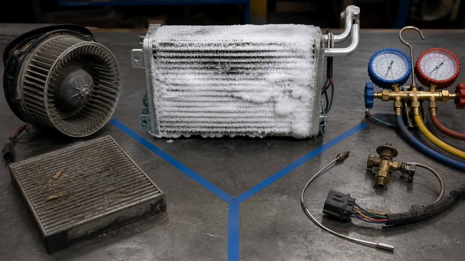
An evaporator that freezes in a tractor, excavator, loader or other heavy-equipment cab is showing an outcome, not naming a failed part. First separate three branches: low airflow across the coil, low evaporating pressure caused by refrigerant or metering conditions, and a temperature-sensing/control failure that allows the coil to run below freezing too long. Dust, cab sealing and long steady-duty cycles make off-highway diagnosis different from room air conditioning.
For parts matching, provide Elecdura the machine model/serial, evaporator, TXV and sensor OE numbers, filter and coil photographs, icing pattern and timing, airflow, temperatures, pressures, ambient and work duty through the automotive and mobile A/C parts programme.
Three-branch diagnosis at a glance
Branch
Evidence to collect first
Common possibilities
Low airflow
Filter/coil/blower condition, vent flow, door position, icing across face
Sensor value and location, command states, clutch/compressor behaviour
Displaced or biased sensor, wiring fault, thermostat/control logic, stuck relay/valve
More than one branch can be present. A dirty filter can lower airflow while an incorrectly placed sensor fails to detect the coldest coil zone.
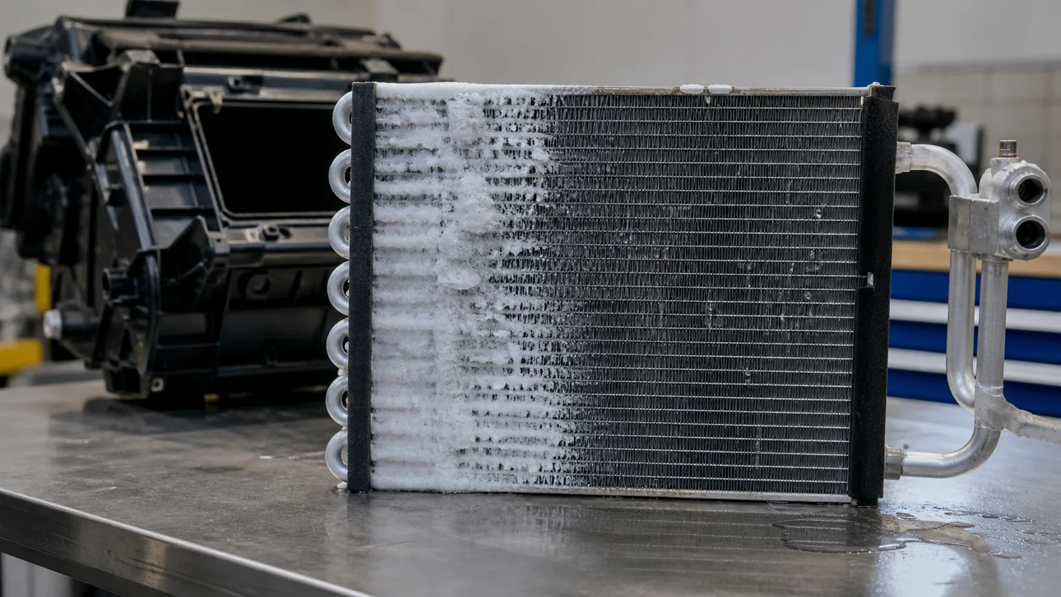
Icing location, spread and time-to-freeze help separate airflow, refrigerant and control causes.
Safety and baseline information
Refrigerant recovery, opening and charging require trained personnel, approved equipment and compliance with applicable rules. Keep hands, tools and leads away from belts, compressor drive and blowers. Do not release refrigerant or use open flame. Some electric compressors operate at hazardous voltage and require vehicle-specific isolation.
Before thawing evidence away, record ambient temperature and humidity, cab starting temperature, sun load, engine speed, recirculation/fresh-air setting, blower speed, work duty, time to first frost, time to airflow loss and whether cycling or shutdown restores operation. Photograph the accessible coil and lines without dismantling a live pressurized system.
Confirm that ice—not a door or blower fault—is stopping airflow
A complaint may be “air gets weak after an hour.” Check vent temperature and airflow trend, blower sound, speed response and distribution doors. If the blower sound remains strong while vent flow falls, an iced/blocked coil or closed door becomes more likely. If sound and current change, investigate the blower circuit and wheel.
After the machine is safely shut down, observe whether meltwater and airflow recovery correspond to thawing. A plugged drain can hold water in the case and promote re-freezing or microbial debris, but condensation alone does not prove freeze-up.
Branch 1: low airflow
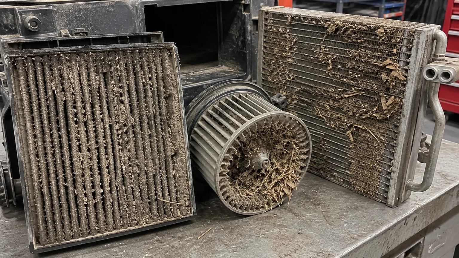
Inspect the cab filter and housing seal. A filter packed with dust, chaff or pollen reduces heat delivered to the evaporator. A missing or poorly fitted filter can load the coil itself. Do not judge only the visible surface; dust can mat between fins and around the blower wheel.
Check evaporator face cleanliness and fin condition with the housing opened according to the service procedure. Use approved low-damage cleaning; aggressive compressed air, pressure washing or tools can fold fins, drive debris deeper or wet electronics. Verify the drain is open and routed away from dust entry.
Inspect blower wheel for packed vanes, slipping hub, broken blades, wrong rotation and motor drag. Test voltage and ground under load and compare current and speed to application information. Elecdura’s blower amperage and airflow guide explains why a motor can spin yet move too little air.
Verify recirculation and fresh-air doors, foam seals, ducts and louvers. A door can appear commanded while linkage or actuator stalls. Off-highway cabs with damaged door/window seals admit dust and humid air continuously, changing both filter life and frost load.
Filter bypass, a packed blower and a dirty coil can combine to reduce heat transfer and trigger icing.
Branch 2: refrigerant pressure and metering
Low suction pressure can correspond to a coil temperature below freezing, but suction pressure alone cannot diagnose charge. Record high and low pressures only under the manufacturer’s test conditions with ambient, humidity, engine/compressor speed, blower, doors and condenser airflow. Interpret the refrigerant’s pressure-temperature relationship and system architecture.
An undercharged system from a leak can starve part of the evaporator and create frost near the inlet, but restriction or TXV behaviour can look similar. Overcharge, air/non-condensables, poor condenser airflow and compressor-control faults often produce different patterns yet can disturb control. Recover and weigh charge only when the diagnostic procedure calls for it.
For a thermostatic expansion valve, inspect sensing-bulb attachment, position, insulation where specified, equalizer connection and valve application. A loose bulb that senses warm air may overfeed; other faults or restrictions may starve the coil. Moisture can freeze at a restriction. Do not replace a TXV based only on frost at the valve.
Fixed-orifice systems need the correct orifice size and orientation, clean screen where present and proper accumulator operation. Variable-displacement and electronically controlled compressors add command, valve and sensor data. Match the diagnostic method to the machine, not a generic manifold chart.
Branch 3: evaporator sensor, thermostat and control
Many systems prevent freeze-up by monitoring evaporator temperature or pressure and cycling or reducing compressor capacity. Identify whether the machine uses a capillary thermostat, thermistor, pressure switch/transducer, control module or combination. Obtain the wiring and control description.
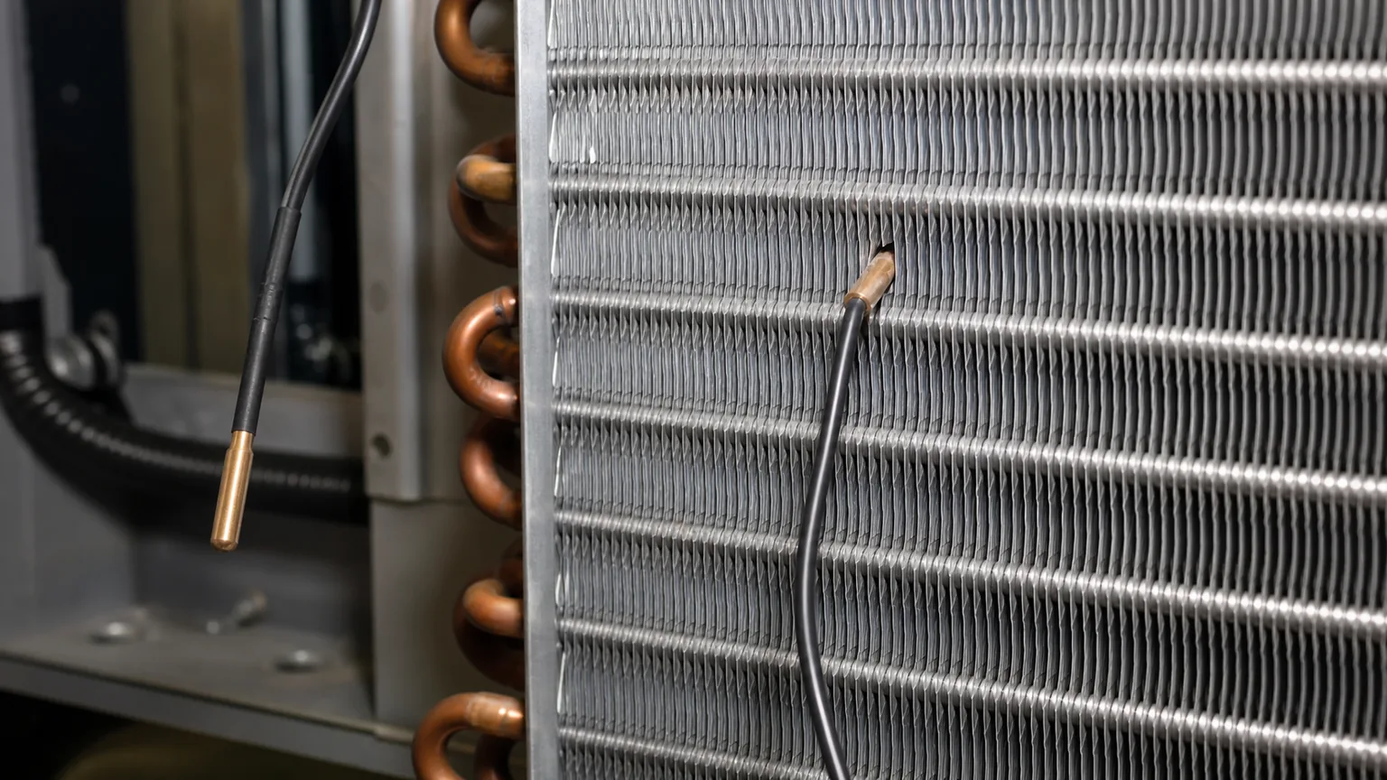
Inspect sensor location and contact. A probe pulled out of the fins, placed in the wrong row, insulated from the coil, bent during cleaning or attached to a replacement evaporator differently can report warmer than the coldest area. Compare scan or measured value with an independent temperature sensor positioned according to service information.
Check wiring, connectors, reference voltage, ground and signal through the approved test. Observe commanded compressor/clutch/control-valve state as the coil approaches the cutout point. A welded relay, bypassed thermostat or aftermarket wiring may keep a clutch engaged even when the controller requests off.
Sensor depth and position determine whether the controller sees the coldest representative coil region.
Use icing pattern as a clue, not a verdict
Uniform frost spreading across most of a dirty coil supports low airflow or an ineffective freeze-protection control, but exact appearance depends on circuit design. Frost concentrated near the inlet may be consistent with a starved circuit, restriction or low charge. Ice beginning where a sensor is absent or displaced may support a control problem.
Record the pattern early, because continued operation can cover the whole coil and erase its origin. Also photograph the suction line, TXV/distributor and case. Surface temperature should be measured with tools and emissivity/contact methods suited to the material; a shiny metal infrared reading can mislead.
Off-highway contamination and duty-cycle effects
Harvest dust, chaff, quarry fines, fertilizer, smoke and oily aerosols can rapidly block a compact cab evaporator. Long low-engine-speed work, door opening, pressure washing, night operation and very humid conditions change loads. The machine may freeze only during one attachment or work cycle.
Inspect filter grade, fit and service interval against the environment. A more restrictive filter can protect the coil but may overload an undersized blower when dirty; use approved parts and monitor condition. Restore cab sealing and clean recirculation grilles. Elecdura’s agricultural machinery and construction machinery cooling programmes treat HVAC as part of the full dusty-duty thermal system.
Match replacement parts as a system
An evaporator must match OE/application, core dimensions, fin density, circuiting, tube and header layout, inlet/outlet connections, TXV/manifold interface, drain and housing mounts. A denser or differently circuited coil may change airflow, pressure drop, refrigerant distribution and sensor response even when it fits the case.
Match TXV refrigerant, capacity/application, superheat specification where provided, bulb/equalizer design and connection geometry. Match sensor curve, connector, lead length and specified fin position. Match blower voltage, wheel diameter/width, rotation, current and housing. Preserve air seals so air passes through—not around—the coil.
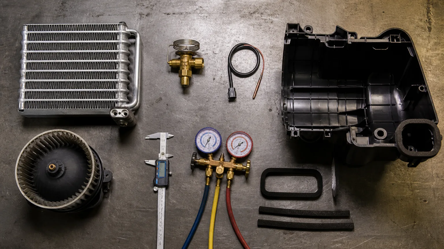
Evaporator, metering device, sensor, blower and housing seals must operate as one validated assembly.
Three-branch diagnostic sequence
Document complaint timing, duty, settings, temperatures, airflow and icing pattern.
Inspect filter, coil, blower, doors, ducts, seals and drain.
Restore verified airflow before interpreting refrigerant pressures.
Identify refrigerant architecture and collect approved pressure/temperature/charge evidence.
Inspect TXV/orifice and sensing/equalizer details under the service procedure.
Verify evaporator sensor/thermostat value, location, wiring and cutout command.
Repair the confirmed cause and validate through the original duty/time window.
Measure airflow without relying on hand feel
Hand feel at one vent is inconsistent and changes with louver direction. Where service information provides a method, use an anemometer, pressure measurement or calibrated comparison at defined vents and blower settings. Record cab voltage, engine state, filter installed and door positions. Compare left/right or upper/lower outlets to reveal a duct or blend-door problem.
Measure blower supply voltage and ground drop under load at each commanded speed. Record motor current after stabilization and compare with the correct wheel installed. High current can accompany drag, a packed wheel or electrical problems; low current can accompany low voltage, open windings, a missing/slipping wheel or control limitation. Current alone is not airflow.
Inspect air bypass around the evaporator. Missing foam, warped access covers or an incorrectly sized replacement coil can allow the blower to move plenty of air at the vents while too little crosses the active fin surface. Bypass also makes the sensor and outlet-temperature evidence less representative. Restore the housing before refrigerant diagnosis.
Clean the coil without creating another failure
Identify whether contamination is dry dust, chaff, oily film, biological material or compacted mud. Vacuum loose debris in the direction that avoids drawing it deeper. Use only cleaner compatible with aluminium, coatings, plastics, seals and electronics, and control liquid so it exits through the drain rather than soaking the cab. Follow environmental rules for contaminated wash fluid.
Do not direct high pressure at fragile fins or tubes. Straighten only limited bent fins with suitable tools and adequate access; extensive folding may require replacement. Protect the sensor and capillary tube and document their original positions before removal. After cleaning, verify drain flow and dry the assembly before judging temperature behaviour.
If oil coats the evaporator, locate the source. Refrigerant-oil residue near a joint may indicate a leak; external hydraulic oil, cab products or dust-binding contaminants can enter through the air path. Cleanliness improvement without leak testing can make a refrigerant fault temporarily less visible.
Interpret temperature and pressure together
Use the refrigerant’s correct pressure-temperature relationship to estimate saturation conditions, but recognize that pressure at the service port is not exactly every point inside the evaporator. Add measured air entering and leaving the coil, line/coil temperatures and sensor value. Temperature difference changes with humidity, airflow, load and compressor control.
A low-side pressure that appears “low” may be normal during reduced load or variable-compressor operation, or abnormal when paired with poor airflow and frost. A high-side reading depends strongly on ambient and condenser airflow. Always confirm radiator/condenser fan operation and external stack cleanliness because high head pressure can cause control responses that complicate the original complaint.
Superheat or subcooling calculations are meaningful only where the system architecture and service procedure support them, using accurate pressure and temperature at defined points. A TXV system, fixed-orifice system and accumulator or receiver-drier arrangement cannot be evaluated by one universal target.
Check for intermittent control failures
Freeze-up often takes long enough that a quick workshop test passes. Use scan data or logged measurements where available: evaporator temperature, ambient, refrigerant pressure, compressor request, clutch or control-valve command, blower command and relevant door position. Correlate the first frost and airflow decline with these traces.
Wiggle testing is performed only where safe and under the electrical procedure. Inspect connectors for water, fertilizer or dust ingress, terminal spread, corrosion, rub and poor repairs. A thermistor may read correctly at room temperature but drift when cold; compare its resistance or signal across specified temperature points rather than replacing it from one reading.
A capillary thermostat depends on correct bulb or tube placement and mechanical condition. Do not kink, cut or heat it. Electronic controllers may impose minimum on/off times, compressor protection and sensor-substitution strategies. Read fault codes and service descriptions before bypassing any control. Temporary bypass for diagnosis, if permitted at all, must be controlled and removed; it is not a repair.
Replacement incoming inspection
Before installation, compare box and unit labels, OE cross, core size, fin pitch, circuits, tube/header and manifold, TXV mounting face, pipe size/orientation, sensor location, drain clearance, frame and foam-seal surfaces. Protect capped refrigerant connections from moisture. A new receiver-drier or accumulator is handled under the supplier procedure and opened only when the circuit is ready.
Check the evaporator for shipping twist, crushed fins, cracked tubes, damaged O-ring faces and debris. Verify TXV orifice/application and sensor curve/connector separately; a kit label can hide one wrong included component. Record lot numbers so a later claim can connect the complete assembly.
Maintenance that prevents repeat freeze-up
Set filter and coil inspection intervals from actual dust loading, not passenger-car mileage. Record differential restriction or blower/airflow baseline where practical and shorten the interval during harvest, quarry or demolition seasons. Keep doors and windows closed when cab pressurization is intended, and repair seals that pull dust past the filter.
Train operators to report the time-related pattern before airflow disappears completely. Increasing blower speed or shutting A/C off briefly may change symptoms but does not repair the cause. Service teams should capture settings and conditions before thawing, then return the machine only after it exceeds the original duty window without frost.
Validation after repair
Begin with a clean filter/coil and known blower/door operation. Evacuate, charge and leak-test by the maker’s procedure if the circuit was opened. Record ambient/humidity, cab starting temperature, engine speed, blower/recirculation, pressures where required, centre-vent and evaporator-sensor temperatures, compressor command and condensate drain.
Run long enough to exceed the original time-to-freeze under a representative load while monitoring safely. Confirm stable airflow, appropriate compressor modulation/cycling, no new frost pattern, unobstructed drain and acceptable cab pull-down. Recheck sensor attachment and housing after vibration.
Warranty evidence
Include machine model/serial and hours, part and lot numbers, install date, refrigerant/oil and charge procedure, ambient/duty, filter and coil condition, blower voltage/current and airflow evidence, pressure/temperature data, icing sequence, sensor location/value and commanded states. Photograph seals, housing, TXV/bulb/equalizer and returned parts.
A replaced evaporator should not automatically be called defective because ice formed. Classify airflow restriction, refrigerant leak/charge, metering, sensor/control, wrong part/fitment, contamination, drain/housing and confirmed component fault separately. Preserve the part capped and clean for analysis.
Evidence should identify the failing branch before parts are replaced and again after validation.
Frequently asked questions
Does low refrigerant always freeze the evaporator?
No. Undercharge is one possibility, but airflow, restriction, metering, compressor control and sensor faults can produce freezing. Diagnose the system.
Can I diagnose charge from suction pressure?
No. Use the machine-specific method and consider refrigerant, ambient, load, compressor control, high-side data and charge evidence.
Why does airflow return after shutdown?
Ice may melt and reopen the coil, but door or blower thermal faults can also reset. Document meltwater, timing and blower behaviour.
Can a universal evaporator be substituted?
Only with engineering validation of refrigerant, capacity, circuit, pressure drop, airflow, connections, sensor and housing interfaces.
Should the TXV be replaced with the evaporator?
Follow the equipment and component procedure. Replace it when contaminated, faulty, incompatible or required, not merely because the evaporator was removed.
Diagnose ice through airflow, pressure and control
Heavy-equipment freeze-up becomes manageable when the technician records the pattern and timing, restores airflow, interprets refrigerant data in context and verifies that the sensor and controller see the real coil temperature.
Send Elecdura the machine identity, OE references, photos and measured evidence. We can match the evaporator, TXV, sensor, blower and housing interfaces for a controlled replacement.