You are here:Home » Resources » Blog » Industry Insights » Off-Highway Reversing Fan Systems: Blade Pitch, Drive Type, Purge Cycle, and Cooler-Stack Protection
Off-Highway Reversing Fan Systems: Blade Pitch, Drive Type, Purge Cycle, and Cooler-Stack Protection
Views: 0 Author: Elecdura Publish Time: 2026-08-31 Origin: Site
An off-highway reversing fan is a matched cooling system, not a blade-only replacement. Before specifying one, confirm the machine and engine, fan diameter and available envelope, hub or motor interface, normal rotation, airflow direction, blade pitch range, drive type and power, controller inputs, purge frequency and duration, shroud clearance, cooler-stack arrangement, guarding, and the debris being removed. A fan that reverses successfully can still overheat the machine, damage the stack, or throw debris toward vulnerable components if the retrofit is not engineered around the complete duty cycle.
Reversing fans are valuable where chaff, dust, fibers, leaves, or light debris rapidly block the grille and cooler faces. They can reduce manual cleaning and help stabilize temperatures between service stops. They do not replace correct cooler-stack maintenance, leak repair, fan and shroud matching, or airflow diagnosis. If a stack is oil-soaked, internally restricted, packed with wet clay, or damaged, a purge cycle may move little material and can create false confidence.
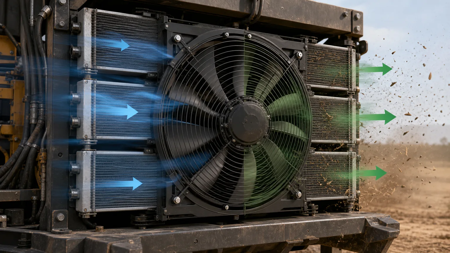
Reversing airflow can eject loose surface debris, but results depend on the fan, drive, shroud, stack, contamination, and purge strategy.
What a reversing fan actually changes
A conventional fan has a blade geometry and rotation chosen to move air in one normal direction. A reversing system changes airflow for a short purge period. Depending on the design, it can change blade pitch while rotation continues, reverse motor rotation, switch a hydraulic drive, or use another controlled mechanism. These methods are not interchangeable from a control or hardware standpoint.
Architecture
How reversal is created
Key matching questions
Variable-pitch fan
Blades rotate through neutral to an opposite pitch while the drive can continue rotating in the same direction.
Voltage, power, connector, protocol, current limit, rotor stop logic, blade suitability and environmental rating.
Complete OEM or engineered retrofit kit
Fan, drive, controller, sensors, harness/valves and brackets are validated together.
Machine and engine application, software, installation envelope, cooler stack, safety interlocks and warranty support.
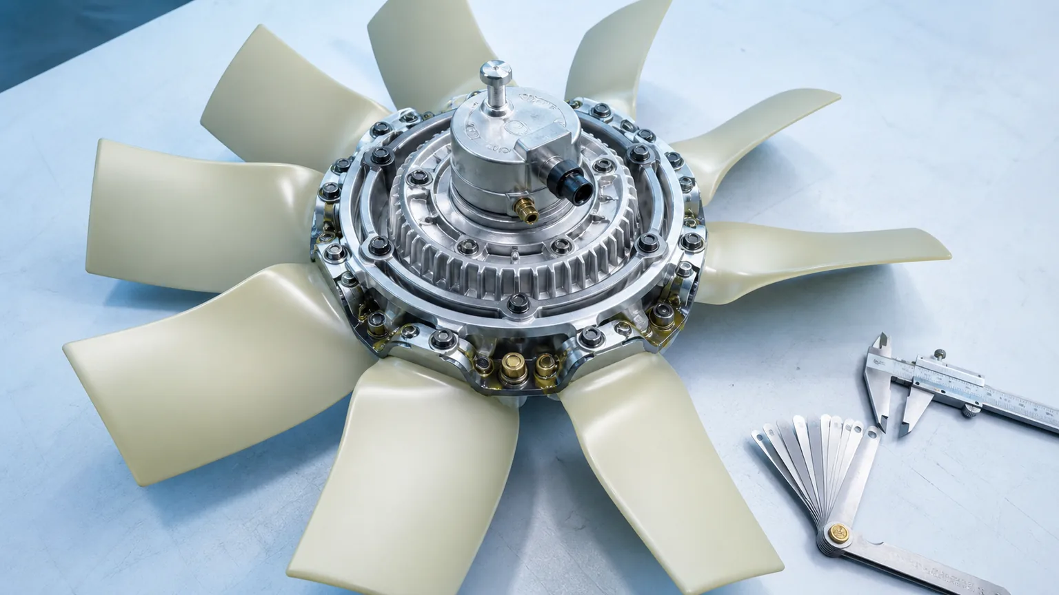
Variable-pitch systems are common because they can create reverse airflow without reversing the engine-driven hub. The blade mechanism, bearings, actuation, and controller add identification fields that a fixed-pitch blade does not have. Hydraulic and electric systems can be effective but must manage the mechanical and electrical stress of stopping and changing direction. Never assume a conventional blade is approved for both rotations.
Start with the contamination, not the fan catalogue
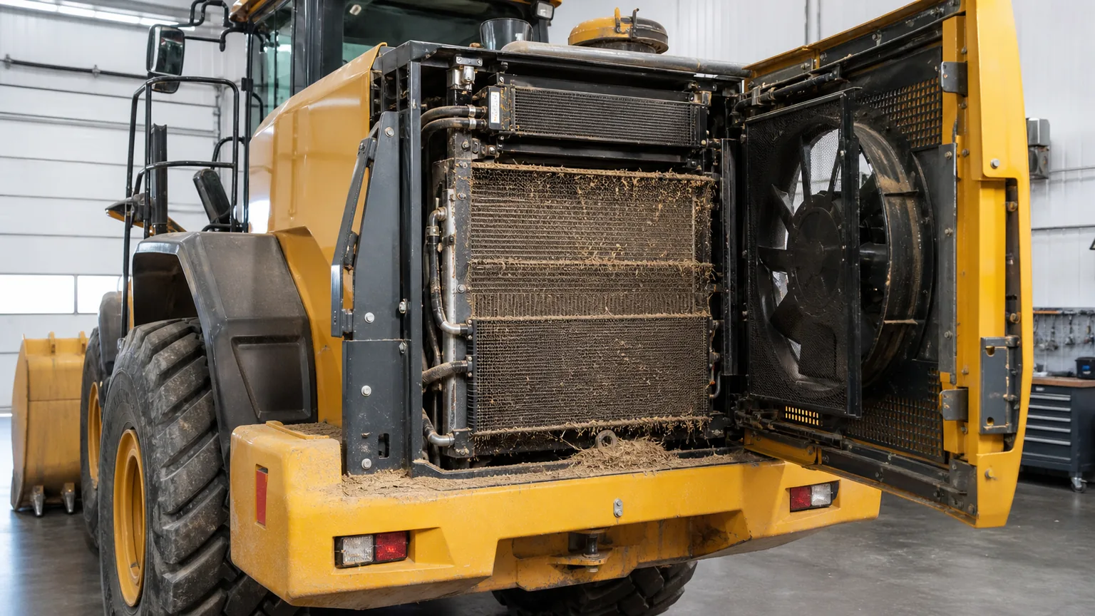
The material blocking the stack determines whether reverse airflow is likely to help. Dry chaff, seeds, grass, paper, light leaves, sawdust, and loose mineral dust can often be expelled if airflow reaches the dirty face. Fibrous contamination may bridge fins and guards. Oily dust adheres to surfaces. Wet clay and packed mud can become too dense for an air purge. Bent fins, internal scale, and blocked coolant or oil passages are not removed by reversing the fan.
Record where contamination first accumulates. A protective screen may load before the condenser. The gap between two stacked coolers can trap material that is invisible from the front. A hydraulic oil leak can coat the downstream face. Missing seals may pull dust around a screen and deposit it on one corner. Photographs taken before cleaning, after a normal work interval, and immediately after a purge help determine what the system actually moves.
Identify whether the fan normally pulls air from outside through the grille and stack toward the engine or pushes air outward through the stack. Note the order of screens, A/C condenser, charge-air cooler, radiator, hydraulic oil cooler, fuel cooler, and other exchangers. Record shrouds, baffles, seals, doors, and pressure-relief flaps. Air follows leakage paths as well as the intended core.
A purge must move air in the direction that releases debris from the loaded face. If debris is lodged between exchangers, reverse flow through the complete pack may be weak. If a screen is far from the fan or bypass gaps are open, purge air can escape around it. The most powerful fan will not clean a face that is poorly coupled to the shroud.
Also consider where ejected material goes. A reverse plume can strike the cab intake, engine air intake, exhaust aftertreatment, hot surfaces, operators, pedestrians, nearby machines, or a wall in an indoor facility. The installation and operating procedure may need guards, deflectors, location restrictions, or a purge interlock based on vehicle speed and work state.
Useful purge flow must pass backward through the contaminated layers instead of escaping through shroud or stack gaps.
Measure the fan envelope and interface
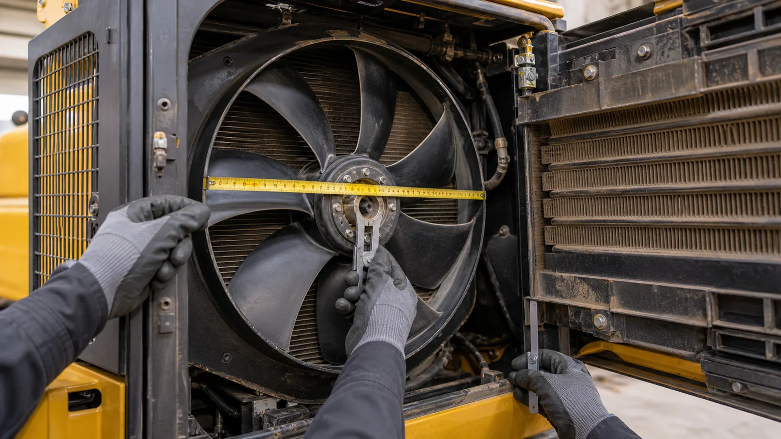
Measure fan diameter, blade count, projected blade width, hub diameter, overall depth, shaft or pilot, bolt circle, fasteners, spacers, and the installed distance to the radiator, shroud, belts, hoses, guards, and engine components. Check axial movement and engine/isolator movement under load. A static workshop clearance can disappear when the powertrain twists or mounts deflect.
For a variable-pitch fan, the blade envelope can change with pitch. The closest point at neutral or reverse may not be the same as in normal cooling. Obtain the supplier’s required shroud and component clearance through the full travel. Do not trim blades or modify a structural hub to make a kit fit.
Rotation must state the viewing side. Record engine or motor speed range and any ratio between the drive and fan. A fan designed for one rotational direction, speed, and torque may not be safe at another. Overspeed, blade fatigue, hub load, bearing load, and noise need consideration. When replacing an existing reversing system, capture the complete fan and hub labels, blade codes, controller, actuator, and software or setting information.
Match the drive type and available power
Engine-driven and clutch-driven systems
An engine-driven fan may be mounted directly, through belts, or through a viscous, pneumatic, or controlled clutch. The retrofit must match the clutch torque capacity, hub/pilot, fan mass and inertia, bolt pattern, and engagement behavior. A heavier or more aggressive blade can overload bearings or a clutch even when diameter is unchanged.
Hydraulic systems
Hydraulic fan performance depends on available flow and pressure, motor displacement and efficiency, control valve, oil viscosity and temperature, return restriction, case drain where required, and system priority. Reversing should follow the approved deceleration and valve sequence. Abrupt direction changes can create pressure spikes, cavitation, hose movement, and mechanical shock. The hydraulic oil-cooler fan direction guide explains the basic relationship among motor rotation, blade, and cooler airflow.
Electric systems
An electric reversible system needs verified voltage, peak/continuous power, wiring, fuse, relay or contactor, controller, connector, communication, speed feedback, thermal derating, and environmental protection. Reversal must be a designed function of the motor/controller. Swapping polarity on an unknown electronic fan is not an acceptable method.
For every architecture, compare the fan curve and drive power at the static pressure created by the installed stack. Free-air flow is not enough. Purge performance matters, but normal cooling remains the primary safety function.
Blade pitch, neutral position, and fail behavior
A variable-pitch fan changes the blade angle relative to incoming air. In normal pitch it provides cooling airflow. Near neutral it can reduce airflow and torque. In reverse pitch it moves air backward for cleaning. The exact positions and actuation method belong to the fan design.
Ask what happens if air pressure, hydraulic pressure, electrical power, or communication is lost. The fan may return to a default cooling pitch, remain in its last position, or move to another safe state. The machine controller must recognize whether cooling is available. A purge command should not leave the fan in neutral or reverse if the actuator sticks or a position sensor fails.
Blade movement must be inspected and maintained according to the manufacturer. Debris, corrosion, damaged seals, poor lubrication, or hub wear can prevent consistent pitch. A daily visual check may be appropriate in harsh duty, but service intervals should follow the system and operating environment rather than a universal schedule.
The hub, actuation, blade code, full pitch envelope, and fail position are as important as fan diameter.
Design the purge cycle around thermal margin
A purge interrupts or reduces normal cooling. The controller therefore needs enough thermal margin to reverse safely. Purging by a fixed timer may work in steady contamination but can be inefficient or risky as ambient temperature and load change. A better strategy can consider coolant, charge-air, hydraulic-oil, refrigerant, or other temperatures; fan demand; engine load; vehicle speed; time since last purge; pressure restriction where measured; and operator request.
Useful cycle questions include:
Does the fan decelerate before pitch or rotation changes?
How long is reverse airflow required to remove the actual debris?
What is the minimum time between purges?
Which temperature or load condition blocks a purge?
Can a purge occur at full engine speed, or is a speed reduction required?
Is vehicle speed, parking brake, transmission state, or operator-zone safety used as an interlock?
What happens if a temperature rises too quickly during purge?
How does the system confirm that normal cooling has resumed?
Begin commissioning with the system supplier’s approved settings. Record temperatures and pressures before, during, and after purge at representative ambient and work loads. Observe the debris plume from a protected location. Adjust only within approved ranges and document the final configuration. A shorter, correctly timed purge can be more effective than a long reversal that heats the machine without removing additional debris.
Commissioning tests that demonstrate function
Baseline the clean machine. Record ambient, engine speed/load, fan command/speed, coolant, charge-air, hydraulic-oil, refrigerant or other critical temperatures with a clean stack.
Inspect mechanical installation. Check fastener torque, hub/pilot, blade and shroud clearance through full pitch, guards, hoses, harnesses, and actuator lines.
Verify normal airflow. Confirm direction, sealing, vibration, noise, and stable temperatures at representative load.
Verify controlled reversal. Observe deceleration, actuation, reverse direction, current or hydraulic behavior, and return to cooling.
Challenge safety logic. Use approved methods to verify temperature inhibit, emergency cancel, loss-of-signal behavior, and fault indication.
Evaluate real contamination. Compare standardized photographs or restriction readings before and after a defined work interval and purge.
Recheck after settling. Inspect fasteners, blade/hub condition, clearances, leaks, wiring abrasion, and controller records after initial operating hours.
Do not stand in the discharge path during a purge. Secure loose tools and covers. Follow lockout procedures before approaching the fan or opening guards. A fan can start automatically from temperature or timer logic even when the engine appears idle.
Incoming and installation quality controls
For a fleet or distributor programme, approve a golden kit that includes the correct fan, hub or motor, controller, harness/valves, brackets, fasteners, guards, labels, instructions, and application configuration. Inspect blade part numbers and direction marks, hub casting and actuator, pilot and bolt dimensions, balance evidence, surface damage, connector sealing, harness length, hose ratings, and package supports.
Require traceability for safety-critical rotating components. If blades or hub parts are mixed across batches, the unit can be difficult to validate. Packaging should prevent blades from carrying carton loads and stop the heavy hub from shifting. Any impact, blade deformation, chipped edge, cracked hub, or missing fastener should trigger quarantine.
Installation documentation should record machine serial, kit and controller numbers, settings, software/configuration version, clearances, rotation/airflow photographs, fastener torque confirmation, baseline temperatures, and commissioning results. That record is essential if a later overheating, vibration, or blade claim must be separated from installation or duty-cycle causes.
Document the full fan envelope and installation datums before selecting or approving a retrofit kit.
When a reversing fan is not the first fix
Resolve these conditions before expecting a new fan to solve the problem:
coolant, oil, or refrigerant leak coating the cooler;
internally restricted radiator or oil cooler;
bent, corroded, or separated fins and tubes;
blocked gap between stacked heat exchangers;
missing shroud, baffle, foam seal, screen, or access panel;
fan clutch, hydraulic motor, pump, belt, or electrical supply fault;
incorrect fan rotation or blade installed already;
engine, transmission, hydraulic, or A/C fault producing excessive heat;
contamination too wet, sticky, or compacted for airflow removal.
A reversible system can complement planned cleaning. It cannot restore a damaged core or correct an internal thermal problem. In severe duty, manual inspection remains necessary because a visually clean front screen can hide debris between cores.
Keep purge settings linked to the installed hardware
Give each commissioned configuration a revision identifier that links the fan, drive, controller, shroud and cooler-stack arrangement to its approved purge settings. When a dealer substitutes a motor, blade assembly or controller, do not carry the previous settings forward solely because the replacement fits. Record which interface changed, which acceptance checks must be repeated and who releases the machine back to work.
Keep the operator's permitted adjustments separate from service-only parameters. Store the approved baseline with the machine record, including the reason for any seasonal change. This makes an unexpectedly frequent purge or a cooling complaint traceable to a hardware change, a setting change or a changed working environment.
RFQ checklist
Category
Evidence to provide
Machine
Manufacturer, model, serial range, engine, application, attachments and duty cycle
Existing fan
Complete labels, diameter, blades, rotation/view side, airflow, speed range and photographs
Interface
Hub/shaft/pilot, bolt circle, spacers, drive/clutch/motor, available power or hydraulic data
Envelope
Shroud and blade clearances, overall depth, engine movement allowance, nearby hoses/guards
Cooler stack
Layer order, dimensions, seals, screens, gaps, normal airflow and access
Contamination
Material, wet/dry/oily condition, accumulation location and cleaning interval photographs
Control
Manual/automatic trigger, sensors, network or discrete interface, interlocks and fail state
Purge target
Starting frequency/duration, allowed engine speed/load and thermal inhibit conditions
Environment
Ambient range, altitude, rain/wash, dust, vibration, corrosion and operator exposure
Commercial
Sample/bulk quantity, destination, documentation, installation support and schedule
Frequently asked questions
Can any hydraulic fan motor be reversed by swapping hoses?
No. Motor design, case drain, shaft loads, valve arrangement, cooling, hose routing, and system control must support reversal. Follow the machine and motor supplier’s circuit and sequence.
Can a reversing fan eliminate radiator cleaning?
No. It can extend intervals by ejecting suitable loose debris, but inspection and cleaning remain necessary. Oil film, packed mud, internal restriction, bent fins, and material trapped between cores may require other correction.
How often should the fan purge?
There is no universal interval. Base it on contamination rate, cooler restriction, temperature/load history, fan demand, machine state, and the system supplier’s limits. Validate the setting under representative work.
Is reverse airflow dangerous to the cooler?
Properly engineered reverse airflow is a normal function of the system. Risk arises from incorrect fan/drive matching, excessive speed or pitch, debris impact, poor clearances, damaged cores, and unsafe discharge direction.
What warranty evidence is useful?
Record machine and kit identity, installation measurements, blade/hub/controller numbers, settings, normal and reverse speed, temperatures, current or hydraulic pressure/flow where specified, contamination photographs, fault logs, service history, and the condition of all returned parts.
Specify the purge around the cooling duty
A successful reversing-fan system preserves normal cooling first and adds a controlled cleaning function second. The correct selection matches the rotating hardware, drive capacity, fan envelope, shroud and stack, control interface, thermal interlocks, contamination, and operating environment. Commissioning then proves that the machine returns to stable cooling after each purge.
For an Elecdura sourcing review, send the machine model and serial range, engine, existing fan and drive labels, hub and envelope measurements, normal rotation and airflow, cooler-stack layout, contamination photographs, hydraulic or electrical data, desired control method, temperature history, quantity, and destination. That evidence supports an engineered fit instead of a risky blade-only substitution and can be linked to a broader high-dust and high-heat cooling programme.