English
Views: 0 Author: Elecdura Publish Time: 2026-08-13 Origin: Elecdura
Clogged radiator symptoms are created by uneven coolant distribution and reduced heat transfer, but overheating by itself does not prove the radiator is restricted. A thermostat that opens late, a damaged water-pump impeller, trapped air, a collapsing hose, poor fan airflow, combustion gas, or external debris across the fins can produce a similar dashboard complaint. Internal restriction becomes credible when several pieces of evidence agree: coolant reaches the radiator, flow does not distribute through the core, temperature mapping shows repeatable inactive sections, and other circulation and airflow faults have been excluded.
The diagnosis matters because cleaning, flushing, and replacement solve different problems. Elecdura supplies automotive and equipment radiators, yet replacing a core will not correct a thermostat, fan, pump, or combustion fault. The correct decision follows the failed heat-transfer function, not the word “overheating.”
The strongest pattern is overheating or rising temperature under sustained load combined with a radiator that receives hot coolant at its inlet but uses only part of the core. Repeatable cold bands or isolated inactive sections on a properly measured thermal map, abnormal pressure behavior, poor heat rejection despite verified airflow, contaminated coolant, and limited improvement after an approved cleaning procedure support internal restriction. One cold lower hose, one infrared spot, or one overheat event is not enough.
Symptom | Why restriction could cause it | Important alternatives |
|---|---|---|
Temperature rises at highway load | Restricted tubes cannot carry and reject required heat | Pump erosion, thermostat travel, hose collapse, combustion load |
Wide cold bands across core | Coolant bypasses blocked tube groups | Measurement angle, airflow pattern, thermostat not open |
Heater stays hot while engine overheats | Heater branch still flows while radiator branch is limited | Low radiator airflow or insufficient core capacity |
Coolant is rusty or contains deposits | Contamination can narrow tubes | Appearance does not quantify restriction |
Upper hose hot, lower area unusually cool | Heat may not distribute through the core | Thermostat closed, low pump flow, air pocket |
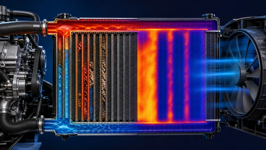
Image 1: Normal and restricted flow distribution through header tanks and parallel tubes.
Coolant enters a header tank and should distribute across many parallel tubes. Scale, corrosion products, sealant, incompatible coolant residue, oil contamination, casting debris, or degraded hose material can reduce the area of individual tubes. Flow then concentrates through the remaining open paths. The active paths may be very hot while blocked groups remain comparatively cold, and overall coolant velocity through the open tubes can increase.
A large temperature drop can mean strong heat rejection, low coolant flow, or a measurement taken before the thermostat is fully open. A small drop can mean high flow, low heat load, insufficient airflow, or poor radiator effectiveness. Map the surface distribution and relate it to mass flow, fan airflow, load, and ambient temperature. Do not reduce a distributed heat exchanger to two hose readings.
Mud, insects, crop fibers, plastic bags, bent fins, paint, and debris between stacked coolers reduce air mass through the core. In a road vehicle, the AC condenser may sit ahead of the radiator. In construction equipment, a charge-air cooler, hydraulic oil cooler, condenser, and radiator may form a dense stack. The off-highway cooling-stack inspection guide explains how debris hidden between cores creates heat rejection failure without internal radiator blockage.
External blockage often produces a more uniform high-temperature core with poor air temperature rise behind it, while internal restriction can create distinct inactive coolant paths. Real systems can have both. Inspect both sides of every layer before deciding that a flush will help.
At idle, the engine may generate little enough heat for the remaining open tubes to cope. During highway driving, towing, climbing, harvesting, or hydraulic work, heat input rises. If temperature increases with sustained load even though airflow is strong, the diagnosis should move toward coolant flow, radiator capacity, combustion load, and system pressure. A fan problem more often becomes severe at low vehicle speed, although heavy-duty fan control faults can also appear under load.
A restricted radiator can have enough capacity for light load but not peak demand. When the throttle or hydraulic load is removed, heat generation falls and the remaining active core catches up. This pattern supports a capacity or flow problem, but it does not isolate the radiator. Record coolant temperature, fan command, engine load, vehicle speed, and ambient condition together.
The heater core is a parallel heat exchanger on many systems. A consistently hot heater while engine temperature rises suggests that coolant is present and at least one branch is circulating. A heater that suddenly turns cold during overheating suggests low level, vapor, pump cavitation, or loss of circulation. Heater evidence helps position the restriction but does not prove radiator tube blockage.
Rust-colored coolant, suspended particles, gel, oil, or stop-leak residue increases restriction risk. The contamination source must be corrected before a new radiator is installed. Oil can enter coolant through more than a head gasket; consult the oil-in-coolant source comparison before condemning a radiator contaminated by another failed component.
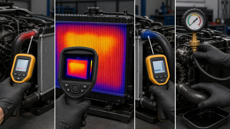
Confirm coolant level and concentration, install the cap, verify the thermostat reaches its commanded or mechanical opening condition, and ensure the fan and airflow system are operating as intended. Reproduce the complaint safely at a stable load. An infrared camera or thermometer reads surface radiation, so clean shiny surfaces, angle, distance, and emissivity can affect results.
Scan from inlet header through the tube field to the outlet header. Look for repeatable regions rather than isolated pixels. Compare tube rows at similar airflow exposure. A restricted group can form a cold band beginning at the inlet header if coolant never enters those tubes. Airflow differences from fan shape or condenser coverage can also create patterns, so correlate the map with the front-of-core condition.
If the thermostat remains closed or pump flow is low, much of the radiator may be cold without being clogged. Verify inlet temperature changes, hose pressure behavior, and service-data expectations. On mapped thermostat systems, scan data and heater control can alter the flow path.
Image 2: Thermal patterns with measurement cautions and alternative causes.
A thermostat can open partially, open late, or be installed incorrectly. An integrated housing may include bypass passages and electrical mapping. The engine thermostat range illustrates why a wax element, mapped thermostat, and complete plastic housing do not share one test or replacement boundary. Compare temperature response with the exact engine procedure.
Inspect drive integrity, pulley or belt condition, leakage, bearing play, electric-pump command, and evidence of impeller damage. A corroded, loose, or cracked impeller can reduce flow under load. Some pumps fail intermittently or only at temperature. Avoid judging pump flow by visible reservoir movement alone.
The pump inlet hose can collapse at higher speed if reinforcement is weak or if the system creates excessive suction. Internal hose delamination can act as a flap. Observe hoses during the complaint when safe, and inspect their internal condition when removed.
At low road speed, fan airflow must pull air through the whole core. Verify blade direction, shroud sealing, motor speed, clutch engagement, module command, voltage drop, and current. Elecdura's cooling fan assemblies are application-specific; blade depth and shroud spacing affect recirculation and core coverage.
Combustion gas can displace coolant and interrupt radiator circulation, creating misleading cold areas. A cap or leak that cannot retain pressure reduces boiling margin. If the reservoir bubbles, follow the coolant bubbling diagnostic sequence rather than assuming the core is the only fault.
Evidence combination | Interpretation | Next action |
|---|---|---|
Hot inlet, repeatable cold core bands, verified thermostat and pump | Internal restriction is strongly supported | Evaluate contamination and clean-or-replace boundary |
Uniformly hot core, weak air temperature rise, dirty fins | Air-side heat rejection is limited | Clean/repair airflow path and retest |
Mostly cold core, inlet does not heat | Coolant is not being delivered | Test thermostat, pump, air pocket, hose |
Cold sections move with fan or measurement angle | Thermal artifact or airflow pattern | Correct method and repeat |
New gas pocket returns after bleeding | Leak or gas intrusion remains | Pressure and combustion-gas diagnosis |
Cleaning is reasonable only when the contamination is compatible with the approved process, the core is structurally sound, the tubes are accessible to the method, and the result can be verified. A simple drain-and-fill does not mechanically restore blocked parallel tubes. Aggressive chemicals can attack aluminum, solder, seals, coatings, or plastic tanks. High uncontrolled pressure can rupture a weakened core.
Contamination is identified and removable by an approved method.
The radiator has no leak, tank distortion, damaged neck, severe corrosion, or separated fins.
The system can be isolated from components that should not receive the cleaner.
Flow or thermal distribution can be measured before and after.
Restriction remains after a controlled cleaning attempt.
Oil, sealant, corrosion, or mixed-coolant residue has made cleaning unreliable.
Tanks, seams, tubes, mounts, cap neck, or transmission-cooler interfaces are damaged.
Downtime and repeat-overheat risk exceed the value of an uncertain repair.
For fleet and wholesale decisions, compare cleaning labor, test time, vehicle downtime, comeback exposure, and warranty traceability with replacement cost. A clean appearance is not the acceptance criterion; restored flow distribution and leak integrity are.
A new radiator can become restricted quickly if the engine block, heater circuit, surge tank, hoses, oil cooler, or transmission cooler still contains incompatible residue. Identify whether corrosion, mixed coolant, oil, sealant, or component debris created the blockage. Clean or replace affected branches with a process compatible with their materials. Record the final coolant mixture and water quality required by the equipment maker.
If the fault followed repeated thermostat problems, inspect the complete bypass and housing path rather than treating the thermostat as an isolated insert. Elecdura's wholesale thermostat selection includes application-specific housings and electrical variants. If airflow tests reveal motor weakness instead, use the radiator fan motor range to define connector, voltage, rotation, and mounting requirements separately from the core.
Idle testing cannot prove a radiator repair for a vehicle that overheats while towing, climbing, harvesting, or powering hydraulics. Recreate a controlled portion of the duty cycle and record engine load, coolant temperature, inlet and outlet temperatures, fan command, ambient temperature, and recovery after load removal. For equipment fleets, use the same measurement points across units so a new core can be compared with known-good machines.
Check the engine cooling parts overview when the evidence crosses several branches. A replacement core should restore heat rejection without hiding a marginal pump, thermostat, pressure cap, or fan that will create another overheat during peak demand.
Keep the original thermal map and repeat it after repair at similar ambient temperature, load, fan state, and coolant temperature. The goal is not to make every tube display the same surface value; it is to restore broad, progressive heat distribution without the inactive bands that accompanied the complaint. Check for leaks after full heat soak and again after complete cool-down, because plastic tank seams and hose joints can change as the assembly contracts.
For machines that operate in dust, crop fiber, or demolition debris, include an air-side cleaning interval and stack-access check in the maintenance plan. Internal restriction and external blockage should remain separate inspection items so a clean front face is not mistaken for verified coolant flow.
Also record coolant additions between services. A small recurring leak can concentrate minerals, introduce air, and encourage operators to mix incompatible fluids. Correcting that maintenance pattern protects the replacement core and makes later thermal comparisons meaningful.
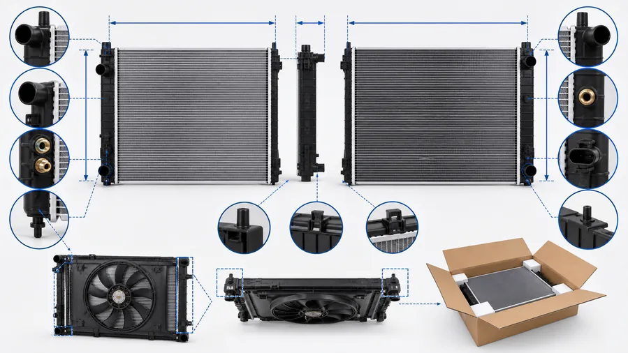
Image 3: Matching points required after restriction is confirmed.
Provide the OE number, vehicle or equipment model, model year, engine, transmission, cooling package, and market version. Record core height, width and thickness; total tank dimensions; inlet and outlet diameter and direction; filler neck or remote-tank design; drain, sensor and vent ports; mounting pins and brackets; fan-shroud points; and any integrated transmission or engine-oil cooler connections.
A catalog image cannot confirm these details. The wholesale radiator program supports application matching, while on-highway applications and off-highway applications require different attention to duty cycle, vibration, stack layout, service access, and packaging protection.
For bulk orders, define pressure and leak-test requirements, fin protection, capped ports, pallet orientation, moisture control, label content, and sampling plan. Inspect the first sample against the OE reference and installation envelope before releasing volume. Use Elecdura's aftermarket sourcing overview to align the part with the intended distribution channel.
Where the radiator shares a frame with a hydraulic or charge-air cooler, photograph the entire stack and provide the equipment serial range. The heavy-duty cooling-stack problem guide helps separate a core restriction from recirculated hot air, damaged seals, or debris trapped in an adjacent exchanger.
Send the OE reference, application, radiator and port photos, core and overall dimensions, cooler connection details, confirmed restriction evidence, and required quantity through the Elecdura contact page. This data separates a correct radiator replacement from an externally similar core that cannot be installed or cooled as designed.
Yes. Remaining tube area may handle light load but not sustained heat input. Pump, thermostat, hose, combustion, and radiator capacity must still be compared.
No. The thermostat may be closed, pump flow may be low, airflow may be uneven, or the infrared measurement may be distorted. Repeatable bands under controlled flow are more useful.
It can remove some compatible deposits, but a drain-and-fill cannot guarantee restoration of blocked parallel tubes. Verify the result with flow or thermal evidence.
Severe system flow loss, low coolant, gas pockets, or pump cavitation can reduce heater flow. An isolated radiator restriction may still leave the heater hot because it is on another branch.
Not automatically. Replace it when testing, contamination, overheating exposure, service policy, or application requirements justify it. Confirm the thermostat and housing configuration separately.
Document the inlet-to-outlet temperature pattern again after repair so the final result can be compared with the restricted core under the same operating load.
A clogged radiator is a distributed flow fault, not a synonym for overheating. Confirm coolant delivery, map the full core, verify airflow and pressure, exclude pump, thermostat, hose, air, and combustion faults, then judge whether cleaning can be measured and trusted. Replacement matching begins only after the radiator has failed that evidence-based test.