You are here:Home » Resources » Blog » Industry Insights » High-Ambient A/C Validation: Condenser Fan Static Pressure, Idle Head Pressure, and Bulk Approval Tests
High-Ambient A/C Validation: Condenser Fan Static Pressure, Idle Head Pressure, and Bulk Approval Tests
Views: 0 Author: Elecdura Publish Time: 2026-08-31 Origin: Site
Free-air fan CFM is not enough to approve a condenser and fan for high-ambient duty. The assembly must be evaluated against the restriction of the installed grille and cooler stack, with a known refrigerant charge, sealed shroud, stabilized ambient and engine condition, measured fan voltage/current/speed, application-specific high-side and low-side pressures, line and vent temperatures, and a repeatable pass/fail baseline. For bulk buying, approve a golden sample first, define the test fixture and conditions, then compare production samples to the same protocol.
This approach prevents four common errors: condemning a replacement A/C condenser when the fan cannot create airflow through the stack; blaming the fan when the shroud leaks; accepting a strong free-air fan that collapses under static pressure; and treating one idle head-pressure number as universal across refrigerants, charges, compressors, vehicles, and ambient conditions.
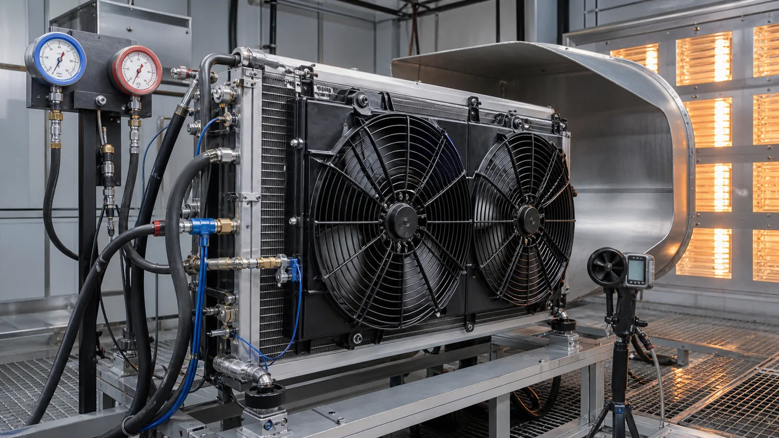
High-ambient approval controls the vehicle state, refrigerant circuit, airflow path, electrical input, and measurement timing.
Why hot idle exposes marginal systems
At road speed, ram air can contribute substantially to heat rejection through the condenser and radiator stack. At idle, the fan and shroud must create almost all useful airflow. Engine-driven compressors may also turn slowly, underhood recirculation rises, electrical supply can be stressed, and heat from the radiator or charge-air cooler can influence the condenser. These conditions reveal weak airflow, excessive restriction, recirculation, charge errors, and control problems that a cool workshop test can hide.
A “high-ambient” test needs a stated ambient target and measurement location. Air temperature in front of the grille, in a shaded weather reading, and inside a hot enclosure can differ. Solar load, humidity, wind, test-cell recirculation, and heat-soak time also affect results. Record the conditions instead of describing the day only as hot.
The objective is not to force every product through one universal temperature. It is to demonstrate that the condenser/fan combination meets the application requirement agreed by the buyer, supplier, and vehicle service data. A city bus idling with frequent door openings, a truck sleeper system, a construction machine, and a passenger car need different test definitions.
Static pressure connects the fan to the cooler stack
A fan curve shows how airflow changes as static pressure rises. Free-air flow is the point with little external resistance. The installed fan operates against the pressure drop of the grille, insect screen, condenser, charge-air cooler, radiator, oil cooler, guards, louvers, shroud, and contamination. As restriction increases, many fans move less air. Two fans with similar free-air flow can behave very differently at the installed operating point.
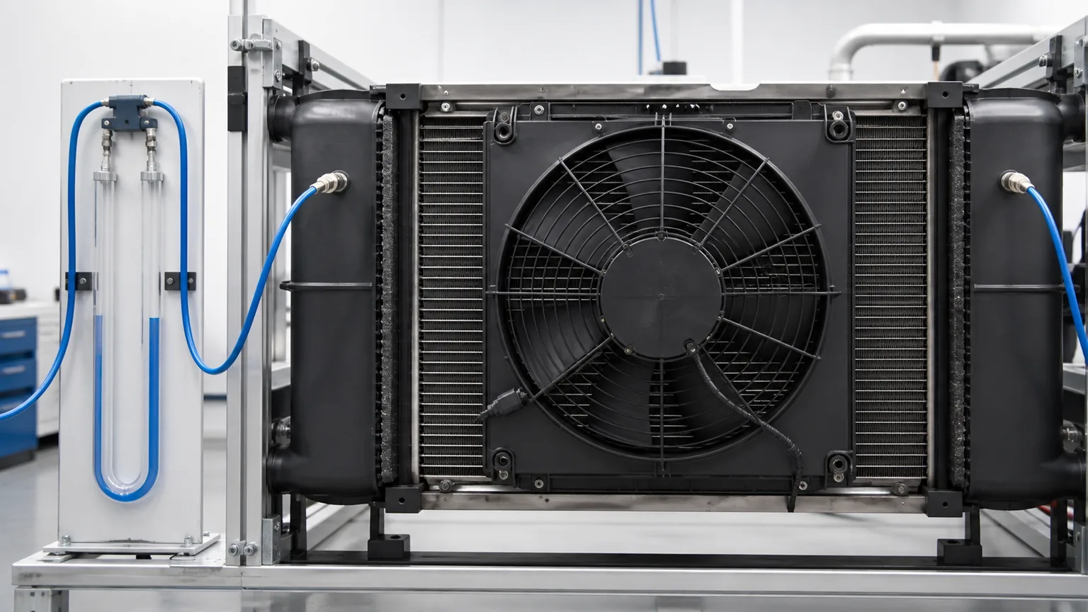
Static pressure can be measured across the relevant stack or component using appropriate pressure taps and a differential manometer. The measurement setup must minimize disturbance and use consistent locations. One pressure tap directly behind a blade tip and another in a calm plenum will not produce a comparable result. A multi-point traverse or validated test fixture is preferable where practical.
Pressure drop alone is not airflow. It becomes useful when combined with a known core/stack characteristic or a calibrated airflow method. For supplier comparison, record the same fixture, shroud, stack, voltage, fan command, ambient density, and instrument positions. The goal is repeatability, not a dramatic number.
Pressure taps and test geometry must remain consistent if static-pressure results are used to compare samples or suppliers.
The variables that must be controlled
Variable
Control or record
Why it matters
Ambient
Temperature at defined inlet location; humidity, wind/air recirculation and solar load when relevant
Changes condenser approach temperature, refrigerant behavior and cabin load.
Vehicle state
Engine or compressor speed, fan command, doors/windows, blower, recirculation, electrical loads, vehicle speed
Defines heat load, compressor capacity and available airflow.
Refrigerant
Correct type, recovered charge mass or approved charge method, oil and contamination status
Overcharge, undercharge, air/non-condensables and oil quantity alter pressures and capacity.
Prevents measurement placement from driving the result.
Acceptance
Application-specific pressures/temperatures, airflow/static pressure, current/speed and durability limits
Creates a decision rather than a collection of data.
Prepare the system before the hot test
Confirm that the test vehicle or rig represents the intended application. Check condenser part number, core dimensions, fin and tube condition, port and receiver/drier configuration, radiator and other stack components, fan/shroud assembly, foam seals, flaps, undertrays, grille, and guards. Small missing seals can allow discharge air to recirculate to the inlet instead of passing through the core.
Inspect both outer faces and the spaces between exchangers. Debris trapped between a condenser and radiator can be invisible from the front. Straighten only minor fin damage with an appropriate method; document larger damage and do not use a damaged sample as the approval baseline.
Recover and charge the refrigerant according to the application procedure if charge accuracy is part of the test. Verify oil history, vacuum process, leak status, and absence of known contamination. Record the recovery/charging equipment used. A high-side pressure result cannot be interpreted confidently when charge mass or refrigerant identity is unknown.
Load-test fan power and ground and confirm the command strategy. For variable-speed fans, record requested and actual speed. For mechanical or fan-clutch systems, record engagement condition and fan speed relative to engine speed where specified. The Elecdura condenser airflow and high-pressure idle guide provides a diagnostic framework for an installed vehicle.
Instrument the test for cause, not just outcome
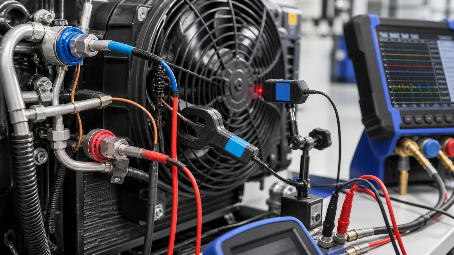
At minimum, record ambient inlet temperature, cabin inlet or return-air condition, vent temperature, high-side and low-side pressure through approved service equipment, fan supply voltage, current, command, actual speed if available, and engine or compressor speed. Add refrigerant-line or heat-exchanger temperatures at consistent points when the procedure supports them.
Pressure should be interpreted with refrigerant type, ambient, operating mode, charge, and temperature. A pressure number by itself does not prove a restriction, weak fan, or failed condenser. Non-condensables, overcharge, metering-device behavior, compressor control, sensor error, and heat load can produce similar patterns.
Temperature sensors must make consistent contact and be insulated from unwanted radiant or airflow effects when appropriate. Infrared measurements can be useful for surface patterns but depend on emissivity, angle, reflections, and access. A contact probe at a defined line position is generally easier to compare across samples.
For airflow evaluation, a velocity traverse over a defined area is more informative than one handheld reading near the blade center. If full airflow measurement is impractical, differential pressure, fan speed/current, and temperature response can create a repeatable comparative signature—but only within the same validated setup.
Record pressures, temperatures, electrical input, and fan speed together so the data can distinguish airflow, refrigerant, and control causes.
A repeatable hot-idle procedure
Document the baseline. Record application, part numbers, refrigerant/oil, charge, fan and shroud, stack condition, ambient and instruments.
Heat soak consistently. Use the approved cell or field method and define when the system is ready to start. Avoid exhaust or hot discharge recirculating into the condenser inlet unless it represents the application.
Set the operating state. Define engine/compressor speed, blower, temperature setting, recirculation, doors/windows, electrical loads, and any auxiliary heat source.
Start synchronized logging. Record pressure, temperature, fan command/speed, voltage/current and relevant vehicle data at the same time base.
Apply the stabilization rule. For example, require readings to remain within an agreed band for a defined period; use the engineering test plan rather than an improvised time.
Observe protection and cycling. Note fan stages, compressor capacity changes, high-pressure protection, clutch cycling, derating and diagnostic codes.
Repeat controlled variations. Where required, compare idle and specified fast-idle, clean screen and defined restriction, or approved fan commands.
Inspect after shutdown. Check connector heat, rub, vibration marks, refrigerant/oil evidence, loose mounts and heat-related deformation.
Safety controls are essential. Use approved refrigerant equipment, protect rotating fans, route hoses and leads away from belts and hot surfaces, ventilate the test area, and follow high-voltage procedures on electrified vehicles. Do not bypass pressure protection to force a test to continue.
How to read common result patterns
Fan or airflow limitation
Possible clues include high-side pressure or outlet temperature worsening at idle and improving with controlled vehicle speed or verified external airflow; low measured fan speed; low voltage at the fan under load; excess ground drop; high current with mechanical drag; low current with weak command; recirculation; open shroud gaps; or an operating point below the required fan curve.
This pattern does not automatically prove the fan motor is defective. The cause may be controller logic, sensor input, wiring, connector heat, blade direction, missing shroud, incorrect assembly, stack restriction, or exhaust/hot-air recirculation.
Condenser limitation
A clean, properly sealed stack with verified airflow can still show poor heat rejection if the condenser has incorrect core geometry, fin density, tube or manifold design, internal restriction, damaged fins, poor refrigerant distribution, incorrect integrated dryer configuration, or wrong application. Compare inlet/outlet temperature patterns, pressure behavior, dimensions, part number, mass and construction to the golden sample and agreed specification.
Charge, contamination, or circuit limitation
Incorrect refrigerant mass, excess oil, air or non-condensables, moisture, a restricted receiver/drier, incorrect valve, compressor control fault, or sensor error can mimic weak condenser airflow. Verify charge and service history before using pressure alone to reject a heat exchanger.
Control limitation
The fan may be physically capable but not commanded to the required speed because of sensor plausibility, calibration, communication, power-management, or software logic. Compare requested and actual speed and confirm whether the system enters a protection mode. On EVs, battery or inverter thermal priorities can change available compressor or fan operation.
From prototype validation to bulk approval
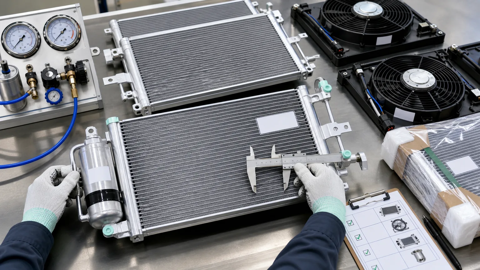
A successful vehicle test does not automatically approve production consistency. Freeze the golden sample identity, drawing, materials and construction, supplier process, packaging, and test signature. Agree which characteristics are critical to quality: core and overall dimensions, port and bracket positions, fin/tube geometry, leak integrity, internal cleanliness, receiver/drier configuration, coating, fan voltage/power/control, speed/current at defined commands, vibration, airflow/static pressure, and traceability.
Define the lot and sampling plan before shipment. The plan can combine 100% checks for identity and obvious damage with sampled dimensional, leak, electrical, vibration, and performance tests. A changed sub-supplier, motor/controller revision, blade, core, brazing process, coating, or packaging should trigger change notification and possible revalidation.
For a condenser, a leak test alone does not establish thermal performance. For a fan, current alone does not establish airflow. Use layered approval: identity and dimensions, workmanship and cleanliness, leak/electrical safety, component performance, then application hot test. Elecdura’s heavy-duty condenser sizing guide explains why face area, thickness, airflow, refrigerant and duty must remain connected.
A bulk lot is compared with the approved identity, interfaces, test signature, packaging, and traceability—not only with a catalogue photograph.
Packaging and handling can change test results
Condenser fins are easily crushed and ports can carry damaging loads if the unit shifts in its carton. Fan shrouds can warp, blade tips can be stressed, and motor/controller connectors can strike packaging. Even when the part is not visibly broken, distortion can reduce blade clearance or airflow and a bent bracket can open a recirculation gap.
Specify fin-face protection that does not press on the core, structural support at approved locations, protected and capped ports, isolated fan blades, connector guards, orientation and stacking limits, and barcode/lot visibility. Sample packages through the expected vibration and handling route, then reinspect dimensions, fins, ports, fan runout, vibration and leak integrity. Packaging controls are discussed further in Elecdura’s cooling-parts return-reduction guide.
Separate invalid runs from failed samples
Define an invalid-run category before testing. A disconnected temperature probe, interrupted logging, changed blower setting or unrecorded opening of the test enclosure should not become a failed-part result. Preserve the raw file, identify the interruption and repeat the run after restoring the agreed conditions. Do not average an interrupted run into the approval dataset.
For a genuine out-of-band result, retain both the suspect sample and the reference sample. Record every adjustment between comparisons so a change in charge, wiring, shroud sealing or test setup is not mistaken for an improvement in condenser production quality.
Minimum approval record
Record section
Required content
Application and sample
Vehicle/rig, VIN/configuration, part numbers, serial/lot, golden sample revision and photographs
Environment
Ambient inlet temperature, humidity/solar/wind or cell settings, heat-soak method and time
System condition
Refrigerant/oil/charge, leak and vacuum process, stack condition, shroud/seals and service history
Operating state
Engine/compressor speed, fan command, blower, recirculation, doors, vehicle speed and electrical loads
Measurements
Pressures, line/air temperatures, fan voltage/current/speed, static pressure/airflow and vehicle data
Timing
Start, stabilization rule, observation duration, cycling/protection events and sample rate
Acceptance
Application-specific limits, comparator/golden-sample band, result and authorized disposition
Post-test
Leak, connector heat, rub/vibration, deformation, fault codes and retained evidence
Common validation mistakes
Comparing free-air CFM only. The installed stack creates static pressure and recirculation.
Testing with unknown charge. Pressure data cannot isolate condenser/fan performance reliably.
Using one pressure limit for every application. Refrigerant, ambient, control and service specifications differ.
Measuring voltage at the battery. The useful value is at the fan under commanded load, with ground drop considered.
Ignoring stabilization and timing. A single early reading can reward a component that cannot sustain the duty.
Removing the production grille or shroud. The test no longer represents the installed restriction and sealing.
Approving one hand-picked sample. Lot consistency, change control and traceability remain unknown.
Letting test-cell discharge recirculate unintentionally. The measured ambient and condenser inlet condition become misleading.
RFQ and validation checklist
vehicle/equipment model, VIN/serial range, engine/drive and destination market;
refrigerant, oil, specified charge and thermal duty;
condenser OE number, dimensions, construction, ports, dryer/sensor and coating;
grille and complete cooler-stack drawings or photographs;
target ambient and operating modes, including idle/fast-idle or EV compressor command;
instrument list, locations, calibration and logging rate;
application-specific acceptance limits and golden-sample comparison band;
lot size, sampling, change notification, traceability and required records;
packaging, destination, annual quantity and implementation schedule.
Frequently asked questions
What head pressure should an automotive A/C system have at high ambient?
There is no universal number. Use the vehicle and refrigerant service data under defined ambient, engine/compressor speed, charge and operating conditions. Interpret pressure with temperatures, fan operation and circuit condition.
Does higher fan current mean better airflow?
No. High current can indicate more power, but also drag, wrong blade, low speed, electrical fault, or operation at a different point. Compare voltage, current, speed, airflow/static pressure and temperature under the same setup.
Can a shop fan prove the condenser is good?
External airflow that improves pressure is evidence of an airflow-related condition, not proof that the condenser meets the application specification. Inspect the installed fan, shroud, stack and condenser, then validate with controlled measurements.
Should the same test be used for R-134a and R-1234yf?
The measurement framework can be similar, but refrigerant-specific equipment, charge, pressure-temperature behavior, service procedures and acceptance data must be used. Do not transfer numerical limits between refrigerants.
How many samples should be tested from a bulk lot?
Set the sampling plan from risk, lot size, process capability, supplier history, critical characteristics and consequence of failure. High-risk identity, leak or safety fields may require stronger controls than cosmetic characteristics. Agree the plan before purchase.
Approve a system signature, not a catalogue claim
High-ambient performance emerges from the condenser, fan, shroud, cooler stack, refrigerant charge, compressor/control, electrical supply, and installed environment. A useful approval test keeps those variables visible and records a repeatable system signature. That evidence can distinguish a fan-limited, condenser-limited, refrigerant-limited, or control-limited result and becomes the reference for production lots.
For an Elecdura sample and bulk-validation review, provide the exact vehicle or rig, refrigerant and charge, condenser and fan OE data, full stack and shroud layout, target ambient/duty, current baseline logs, critical acceptance limits, quantity, and destination. Elecdura can then align the part match, golden sample, test evidence, packaging and lot controls with the real high-temperature operating requirement.