English
Views: 0 Author: Elecdura Publish Time: 2026-08-07 Origin: Elecdura
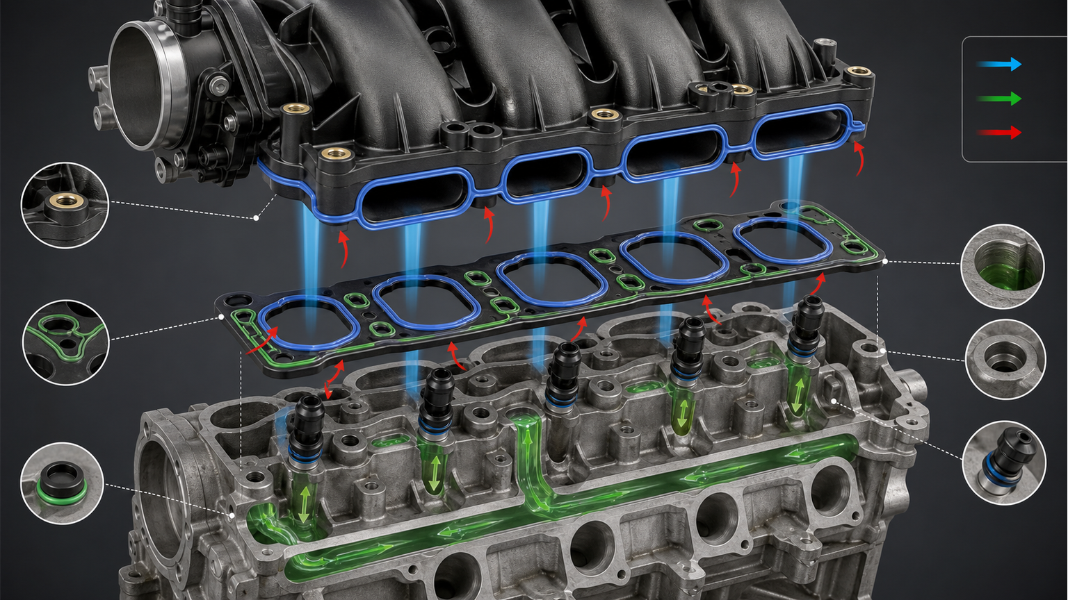
Intake manifold gasket leak symptoms depend on what the gasket is supposed to seal. An air-side leak can admit unmetered air and cause high positive fuel trims, unstable idle, a cold misfire, a whistle, or lean codes. On engines where the intake manifold also seals coolant passages, a different failure can cause external coolant seepage, internal coolant entry, odor, level loss, or overheating. The same gasket set may border both media, but the diagnostic evidence and repair risk are not the same.
Do not order a gasket because the engine idles poorly or loses coolant. PCV and purge circuits, injector seals, throttle-body seals, brake-booster hoses, cracked plastic manifolds, cylinder-head gaskets, coolant outlets, and runner-control shafts can imitate parts of the symptom set. The task is to identify the leaking medium, locate the path, and decide whether the sealing surfaces can support a gasket-only repair or require a complete intake manifold.
Evidence | Air-side gasket leak | Coolant-side manifold leak | Common alternative |
|---|---|---|---|
Fuel trims | Often more positive at idle and improve with load | May be normal unless combustion is affected | PCV, purge, injector seal, low fuel delivery |
Smoke test | Smoke may exit at manifold-to-head joint | Not designed to prove coolant sealing | Throttle, vacuum hose, brake booster, shaft seal |
Coolant level | Normally unrelated | May fall with visible or internal leakage | Outlet, hose, radiator, pump, head gasket |
Cold start | Leak may shrink or expand with temperature | Coolant may enter a port after shutdown | Injector leakage, ignition, compression fault |
Visible wetness | Oil/dust track may mark air leak but is not conclusive | Coolant trace near passage can be useful | Leak running from a component above |
An engine can have more than one fault. A smoke leak at a PCV hose does not rule out a warped manifold flange, and coolant at the bellhousing side may have traveled from an outlet above the manifold. Clean, dry, and recheck the area under controlled conditions.
Aluminum cylinder heads and plastic or aluminum manifolds expand at different rates. Repeated heat cycles load the gasket and mounting inserts. Over-torque can distort a plastic flange or crush a seal; under-torque, wrong sequence, dirty threads, trapped wiring, or missing supports can leave uneven clamp load. A repaired leak may return if the surface or insert is damaged rather than the elastomer alone.
Molded rubber seals harden, flatten, swell, or crack with heat, oil vapor, incompatible cleaner, and time. Coolant contamination and incorrect service chemicals can attack some materials. The replacement material and bead geometry must be correct for the application; color is not a reliable material specification.
A gasket cannot fill unlimited distortion or a crack that opens under heat. Plastic manifolds can warp around bolt bosses, split near seams, or crack at vacuum and coolant ports. Variable-runner shafts can leak air at their pivots. Those faults may be close to the head joint but require a manifold or runner repair, not another gasket.
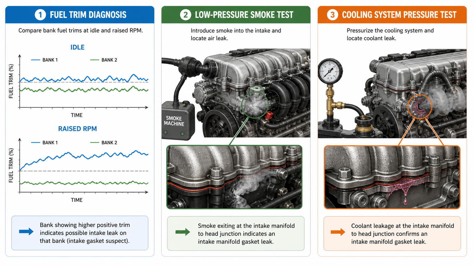
Unmetered air has a larger proportional effect when commanded airflow is low. If short- and long-term fuel trims are strongly positive at idle and move closer to normal as engine speed and load rise, an intake leak becomes plausible. Compare banks. A leak serving one bank or runner group may create bank-specific correction, while a central PCV or purge leak can affect both.
Low fuel pressure, restricted injectors, exhaust leaks ahead of an oxygen sensor, biased airflow or pressure sensors, and fuel composition can also increase trims. Confirm sensor plausibility and the fuel system before treating the trim pattern as proof of a gasket failure.
A sealing gap may change as the head and manifold expand. A cylinder near the leak can run lean at cold idle and stabilize after warm-up. Record cylinder-specific misfire counts and fuel trims from the first start, before heat changes the joint. Ignition, injector, compression, and coolant-entry faults can show the same temperature pattern, so pair the observation with smoke or localized enrichment evidence.
Sound can help identify a leak but travels through plastic ducts and covers. Use a safe listening tool and compare the noise with throttle angle, purge operation, brake application, and PCV changes. Never spray flammable cleaner on a hot or running engine as an improvised leak test.
Modern control systems can correct a moderate leak before the driver notices. Freeze-frame data may show whether the code set at idle, cruise, or load. A leak that matters mainly at idle should not be diagnosed from a highway freeze frame without checking other causes.
Use a cooling-system pressure test at the specified pressure and temperature. Inspect with mirrors or a borescope where safe. Coolant can follow casting ribs, wiring looms, or the transmission housing, so trace upward to the first wet point. The radiator, hoses, coolant outlet, thermostat housing, heater connections, and water pump remain alternative sources.
An internal manifold leak may allow coolant into an intake port, but a cylinder-head gasket, cracked head, EGR cooler, oil cooler, or other engine-specific component can also consume coolant. Inspect spark plugs, cylinder condition, exhaust vapor, cooling-system pressure decay, and combustion-gas evidence using approved methods. No single test should be interpreted beyond its design.
If a cylinder can collect liquid after shutdown, avoid repeated cranking until the engine is inspected. Coolant entering combustion can damage bearings, cylinder walls, oxygen sensors, and catalysts. The urgency is different from a small external seep, even if both originate near the manifold gasket.
Some older engine layouts allow a failed intake gasket to connect coolant and crankcase areas, while many modern dry manifolds do not carry coolant at all. Check the actual casting and gasket design. Do not apply a failure pattern from another engine family. If oil and coolant mix, isolate the engine oil cooler, head gasket, and other interfaces appropriate to that engine.
Record fuel trims, oxygen or air-fuel sensor response, manifold pressure, airflow, misfire counters, coolant temperature, purge command, and runner position. Use the same conditions after the repair. A bank-specific cold pattern creates a stronger test target than a generic lean code with no operating context.
Follow approved procedures to test the PCV, purge, brake-booster, and auxiliary vacuum branches. Pinching an unsuitable hose can damage it or affect safety systems, so use the service method. If trims normalize when a branch is isolated, diagnose that branch before sealing the manifold joint.
Introduce approved smoke at a low regulated pressure. Seal the intake as directed and observe the manifold-to-head joint, injector seals, throttle body, PCV ports, vacuum connections, runner shafts, and manifold seams. Smoke appearing at a drain or vent may be normal for the system design. Excess pressure can create a leak or damage a sensor.
A joint that leaks cold may seal after the engine warms, and a hot plastic crack may close when the engine cools for testing. Use cold and warm evidence where the procedure permits. Residual oil can also hide a small smoke plume, so inspect from multiple angles.
A professional enrichment tool can help confirm that adding a known fuel near a suspected leak changes sensor response. Follow fire-safety rules and never use uncontrolled flammable sprays. The result localizes unmetered air but still requires inspection of the exact gasket, crack, shaft, or hose.
Install the correct adapter, keep pressure within specification, and account for coolant temperature. Observe external joints and pressure decay. If pressure falls without visible leakage, continue with engine-specific internal-leak tests. A pressure drop can also come from the tester, cap adapter, or another cooling component.
Protect open ports from debris. Photograph bolt lengths and bracket positions. Look for compressed or split beads, erosion tracks, surface pitting, cracks, pulled inserts, distorted flanges, coolant staining, and previous abrasive damage. Check flatness using the specified method and limit; a straightedge resting on raised inserts can produce a false result.
Finding | Gasket-only repair | Complete manifold decision |
|---|---|---|
Hardened seal; flat undamaged surfaces | Usually defensible with correct preparation | Not required solely for seal age |
Warped plastic flange or pulled insert | High repeat-leak risk | Replace manifold if outside service limit |
Cracked runner, seam, or vacuum port | Gasket will not correct the path | Replace or use an approved structural repair |
Worn runner shaft or broken flap | Separate runner-control fault remains | Replace assembly when internal parts are not serviceable |
Corroded head surface | Depends on approved repair and measured damage | Manifold alone will not repair the cylinder head |
Elecdura's broad aftermarket program can include a gasket or complete assembly, but the quotation must state the actual scope. Confirm whether seals, runner actuator, sensors, throttle-body gasket, fuel-rail hardware, and mounting fasteners are included. Do not infer contents from a catalog photo.
Remove old gasket material using the approved method. Prevent debris and solvent from entering ports. Aggressive discs can round a plastic flange or remove metal, creating a leak that the new gasket cannot accommodate. Confirm bolt holes are clean and dry where required.
Use calibrated tools and the specified sequence. Some fasteners are torque-to-yield or have application-specific sealant; others are reusable. Replace damaged inserts and brackets. Tightening one end fully before the other can distort the manifold and unload a sealing bead.
A disconnected PCV hose can create a larger leak than the original gasket. Verify purge, brake-booster, vacuum, coolant, fuel, and electrical connections. Route the harness away from pinch points and heat. Replace brittle quick connectors rather than forcing them.
A torn diaphragm or failed separator in the valve cover can create a whistle, unstable idle, high fuel trims, oil consumption, and excessive crankcase vacuum. The sound may travel toward the intake manifold. Test crankcase pressure and the PCV flow path using the engine-specific procedure. Blocking the port without understanding the system can create crankcase pressure and oil leaks. If the PCV function is integrated, confirm whether the repair boundary is a diaphragm kit or a complete cover before adding the intake manifold to the order.
A purge valve that flows at idle when it should be closed can admit vapor and air, alter fuel trims, and cause a hard start after refueling. Compare purge command with actual flow and isolate the line by the approved method. Smoke entering the evaporative-emissions circuit does not prove the manifold gasket is leaking. Record this result in the diagnostic sheet attached to the replacement-parts inquiry.
An injector upper seal can leak unmetered air near a runner, while a restricted injector or low fuel pressure can produce a lean cylinder without any air leak. Inspect injector seats during manifold removal, but do not disturb the fuel system without the required depressurization and fire precautions. A complete aftermarket assembly may not include injector seals, so list them explicitly where the service procedure requires replacement.
Coolant follows gravity and airflow, often collecting along the manifold-to-head seam after leaking from a component above it. Pressure-test the cold system, inspect the highest wet point, and use UV dye only when approved. Compare the cooling circuit with the engine cooling component range and the radiator circuit before labeling the manifold gasket as the source.
Coolant in oil or oil in coolant is serious evidence, but it does not identify the interface. An engine oil cooler, cylinder-head gasket, cracked casting, or manifold passage may be responsible depending on design. Use pressure, combustion-gas, oil-circuit, and component-isolation tests specified for the engine. Do not sell a gasket set on the basis of fluid appearance alone; route unresolved evidence through the technical contact channel with the engine code and test results.
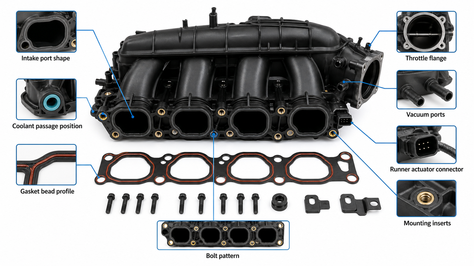
Provide the OE number, vehicle and market, engine code, production date, manifold material, port count and shape, coolant-port layout, throttle flange, injector and fuel-rail mounting, sensor and vacuum ports, runner actuator and connector details, gasket profile, and photographs of both sealing faces. Similar manifolds can bolt on while using different runner calibration or accessory ports.
For on-highway applications, VIN-derived configuration and emissions package can separate variants. For off-highway equipment, include the machine model, engine serial or arrangement information, duty environment, and bracket layout. Use catalog downloads as a reference and verify the physical sample before volume approval.
Check sealing-surface flatness, port alignment, insert security, thread quality, runner movement, actuator attachment, connector keying, vacuum-port dimensions, sensor bosses, internal cleanliness, included gasket identity, and protective packaging. Cap ports and support the housing so transport load does not distort the flange or runner mechanism. Maintain lot and label traceability for warranty analysis.
Unmetered air can make one cylinder or bank lean, often most noticeably at idle or cold start. Confirm with trims, misfire data, smoke testing, and ignition/injector checks.
Some engines route coolant through the manifold joint; others use a dry intake. Confirm the design and trace the first wet point before ordering a gasket.
A temperature-dependent gap may close during the test, and smoke can exit from another normal vent or nearby hose. Combine smoke with fuel trims, operating pattern, and physical inspection.
Reuse depends on flange flatness, cracks, inserts, ports, runner shaft, actuator mounts, and cleaning compatibility. A new gasket cannot correct a warped or cracked housing.
Provide OE reference, application and engine details, front and rear photos, sealing-face and port layout, runner hardware, connector and vacuum ports, required included gaskets or sensors, quantity, and packaging expectations through Elecdura's contact team.
After the leak path is confirmed, send Elecdura the original manifold and gasket OE numbers, engine application, air-side or coolant-side failure evidence, sealing-face photos, measured flange condition, runner and actuator configuration, port layout, included-parts requirement, and order quantity. Those details determine whether a gasket set is sufficient or a complete manifold is needed and prevent an air-leak diagnosis from being mixed with an unrelated runner-control fault.