English
Views: 0 Author: Elecdura Publish Time: 2026-08-13 Origin: Elecdura
AC compressor short cycling means a clutch-controlled automotive compressor engages and disengages more frequently than the operating condition should require. The phrase does not describe every visible clutch cycle. Many fixed-displacement systems cycle normally to control evaporator temperature, while variable-displacement systems may keep the clutch engaged and regulate capacity internally. Diagnosis begins by identifying the compressor and control strategy, then measuring how long each on and off period lasts under a repeatable ambient temperature, blower setting, engine speed, and cabin load.
A rapid cycle can protect the system from low suction pressure, excessive discharge pressure, evaporator freeze-up, clutch-coil heat, or an implausible sensor signal. It can also result from a clutch air gap that opens as the hub warms. Replacing the compressor before finding the command that disappeared can leave the original fault unchanged. Elecdura's automotive AC compressor range includes different clutch, pulley, displacement, control-valve, connector, and mounting configurations; those differences determine what “normal cycling” looks like.
There is no universal number of seconds that proves a fault. Cycling frequency changes with ambient temperature, humidity, airflow across the evaporator and condenser, refrigerant charge, blower speed, cabin temperature, engine speed, and controller strategy. A cycle becomes suspicious when the clutch repeatedly drops out before meaningful cooling develops, vent temperature oscillates, pressure reaches a cutout threshold too quickly, or the command remains on while the clutch releases.
Observed behavior | Most useful first question | Likely diagnostic branch |
|---|---|---|
Command and clutch both switch rapidly | Which input is requesting the cutout? | Pressure, temperature, engine-protection, or control logic |
Command stays on but clutch releases | Is power lost or does the clutch open mechanically? | Relay, wiring, coil heat, air gap, thermal protector |
Low side falls rapidly after engagement | Is charge low or flow restricted? | Leak/charge, expansion device, evaporator airflow |
High side rises rapidly at idle | Is condenser airflow sufficient? | Fan command, fan current, blocked fins, overcharge/non-condensables |
Cooling starts normally, then cycles after time | What changes with temperature? | Clutch gap, coil resistance, icing, module or connector heat |
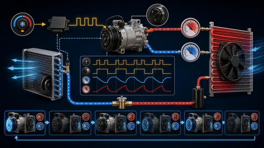
Image 1: Clutch command chain with measurable states at each control point.
This architecture often uses clutch cycling as a normal capacity-control method. The controller may interrupt the clutch when evaporator temperature approaches freezing or when low-side pressure reaches a calibrated cutout. A thermostatic switch, pressure switch, pressure transducer, or control module can provide the decision. The important comparison is not “cycling versus no cycling,” but measured cycling versus the service information for the exact system under the current test condition.
A variable-displacement compressor can reduce pumping capacity through an internal mechanical or electronically controlled valve while the clutch remains engaged. Some systems still disengage the clutch for protection or low demand. Rapid clutch cycling on this architecture can indicate that the controller is reaching a protection boundary even though capacity should normally be modulated. The AC compressor control-valve diagnostic guide explains why poor cooling does not automatically mean the complete compressor has failed.
Hybrid and EV compressors change speed or torque electronically. Their operation must be read through scan data, high-voltage safety procedures, refrigerant pressure, and temperature behavior. A technician should not apply a clutch-cycle diagnosis to an electric AC compressor. Lubricant insulation requirements and high-voltage isolation also make service procedures different.
When the compressor starts, suction pressure falls. If refrigerant mass is low, the pressure can reach the low cutout quickly because the evaporator is starved. A restricted expansion device, blocked inlet screen, collapsed hose, or low evaporator heat load can produce a similar pressure direction. The pressure value must be read together with line temperatures, superheat where applicable, leak evidence, and evaporator airflow.
A low-side gauge reading alone does not establish the correct charge. Overfilling can move the system into a high-pressure problem, increase compressor load, and mask the original leak. Recover and measure refrigerant according to the vehicle procedure when charge quantity must be confirmed. If a leak is found, repair it before evaluating the final cycle pattern.
Discharge pressure rises when the condenser cannot reject heat, the system contains too much refrigerant, non-condensable gas is present, or a restriction traps liquid on the high side. At idle, insufficient condenser airflow is a frequent reason for a rapid pressure rise. Inspect the automotive AC condenser, confirm the fan is actually commanded, and measure fan performance rather than simply listening for noise. A fan can rotate slowly while drawing abnormal current and moving too little air.
The system may cycle the compressor to prevent evaporator icing. A restricted cabin filter, weak blower, closed duct, dirty evaporator, incorrect sensor contact, or thermistor bias can make the measured temperature reach the cutout too soon. Icing may also build gradually, causing good initial cooling followed by declining airflow and repeated cycling. The diagnosis must include airflow volume and evaporator sensor data, not pressure alone.
The engine controller can remove compressor permission during excessive coolant temperature, wide-open throttle, high engine load, unstable idle, low voltage, or another protection condition. Stop-start and hybrid strategies add further interruptions. If the A/C request remains present at the control panel but the engine controller removes clutch permission, the compressor circuit may be responding correctly.
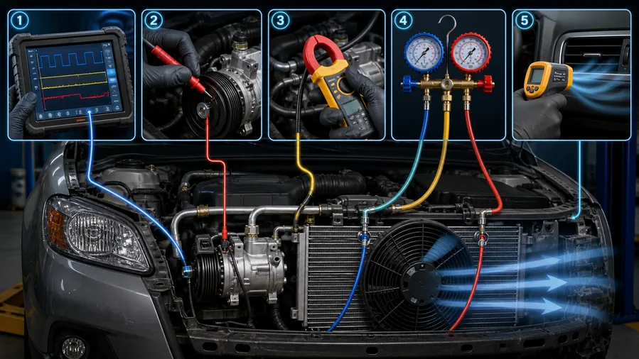
The most efficient test is to record four states at the same time: A/C request, controller clutch command, voltage at the clutch circuit, and physical hub engagement. Add low- and high-side pressure, evaporator temperature, and vent temperature when the equipment supports synchronized recording. This prevents a mechanical release from being mistaken for an electronic decision.
The controller is ending the cycle. Identify which input crossed a boundary: low pressure, high pressure, evaporator temperature, coolant temperature, engine load, or voltage. An AC pressure switch or sensor should be evaluated by its signal and reference circuit, not by replacing it whenever pressure-related cycling occurs.
Trace the relay, fuse, connector, harness, ground, and control output under load. A digital meter can display battery voltage through a high-resistance connection when the coil is disconnected, yet the voltage can collapse when current is demanded. Back-probe safely and use an approved load or voltage-drop method.
Measure clutch-coil current and resistance at cold and hot conditions. A coil winding can open as temperature rises. Inspect the clutch air gap and hub movement according to the compressor procedure. Excessive gap may allow cold engagement but prevent the magnetic force from pulling the hub in after thermal expansion. The recent compressor clutch not engaging guide covers static electrical and air-gap tests; this article adds the time-dependent evidence needed for cycling complaints.
Image 2: Synchronized low-side, high-side, clutch-command, and vent-temperature traces.
Record ambient temperature and humidity, engine speed, blower speed, recirculation setting, door and window position, initial cabin temperature, and time since start. Place pressure and temperature sensors before drawing a conclusion. A test performed in a cool workshop with low heat load may create normal cycling that does not reproduce a hot-idle complaint.
Check the cabin filter, blower output, evaporator cleanliness where accessible, condenser fins, debris between stacked heat exchangers, fan direction, fan speed, shrouding, and air seals. The condenser fan range includes application-specific blade, motor, connector, and mounting arrangements; a visually similar fan is not proof of correct airflow.
After the system has stabilized, static pressure should be interpreted against refrigerant temperature and the specified refrigerant type. A static reading cannot confirm charge quantity because liquid and vapor can coexist across a range of quantities. A very low static value can support major refrigerant loss, but charge confirmation still requires recovery and measurement.
Watch the pressure direction and command state from the first engagement. Note the exact value or temperature at which the command turns off and on. Repeating thresholds suggest intentional control. Irregular release with unchanged command suggests electrical or clutch behavior. Compare the pattern at idle and at the specified elevated engine speed while maintaining safe test conditions.
Compare a pressure-sensor signal with calibrated gauges. Compare evaporator temperature data with a measured surface or air temperature where the service procedure permits. Check reference voltage, ground integrity, connector tension, and signal response. Do not permanently bridge a safety switch or command a clutch against an unsafe pressure condition.
If the pattern supports charge error, recover the refrigerant with approved equipment, record the recovered mass, inspect the oil and refrigerant for contamination, repair leaks, evacuate to the specified method, and recharge by mass. Pressure-charging by guesswork creates unreliable evidence.
Pressure and temperature pattern | Most plausible branches | Confirmation |
|---|---|---|
Low side falls quickly; high side remains modest | Low charge, restriction, low evaporator load | Leak test, recovered mass, superheat/temperature evidence, airflow |
High side rises quickly at idle | Low condenser airflow, overcharge, non-condensables, restriction | Fan command/current, airflow, recovered mass, temperature profile |
Both pressures equalize unusually fast after release | Low compressor pumping or internal leakage | Capacity test, displacement/control-valve diagnosis |
Vent gets cold, airflow then declines | Evaporator icing or airflow restriction | Evaporator temperature and airflow trend |
Command stays on; clutch releases hot | Coil open, excessive air gap, connector or relay heat | Hot voltage, current, resistance, gap measurement |
A leaking seal or hose should be repaired without condemning a compressor that passes pumping, noise, oil, and clutch tests. A failed relay, sensor circuit, fan, or connector belongs to its own service branch. A compressor replacement becomes justified when internal pumping, seizure, clutch, pulley, coil, housing, or control components have failed and the available service policy makes complete replacement safer than subcomponent repair.
When a compressor has produced metal or severe oil degradation, the decision expands to system contamination. Review the AC compressor contamination guide and determine which hoses, condenser design, expansion device, receiver-drier, and flushing procedures apply. The compressor kit versus bare compressor comparison explains why a lower unit price can lead to repeat failure when required protection components are omitted.
A saturated receiver-drier can release desiccant debris or fail to protect the circuit after the system has been open. A restricted expansion device can starve the evaporator and drive suction pressure toward a cutout. The receiver-drier replacement guide explains when exposure, contamination, or component replacement makes the drier part of the repair rather than an optional add-on.
Oil specification and total system quantity affect lubrication, heat transfer, and refrigerant circulation. Too much oil can reduce heat-exchanger performance; too little can damage the compressor. Use the label and service information, then consult the compressor oil amount and type guide. Do not transfer the POE requirement of an electric compressor to a conventional clutch unit or assume every PAG viscosity is interchangeable.
After repair, test cold start, hot idle, elevated engine speed, recirculation, fresh-air mode, several blower speeds, and a warm restart. Confirm that fan staging and pressure cutouts remain stable as the system heat-soaks. Inspect line frost, clutch temperature, connector heat, and condensate flow. This final envelope test is what separates a repaired short-cycle fault from a symptom temporarily hidden by a cool workshop.
Document the before-and-after cycle duration and the conditions that created each cutout. For fleet work, preserve the pressure graph and recovered refrigerant mass with the repair record. That trace gives warranty teams evidence that the compressor was not replaced merely because its clutch moved repeatedly, and it helps identify a recurring leak, fan-current problem, or control input if the complaint returns.
Label every measurement with the refrigerant type and test-point location. A trace without those details can be misread when different workshops, climates, or vehicle configurations are compared.
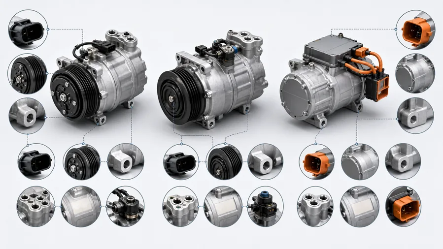
Image 3: Repair path from observed cycle to the correct replacement boundary.
For a clutch compressor, provide the OE number, vehicle, model year, engine, refrigerant, pulley diameter and groove count, clutch connector, mounting ears, port style and orientation, rear-head configuration, and control-valve connector where used. Confirm whether oil is prefilled, its specification and quantity, and whether the shipment includes O-rings, a drier, expansion device, or installation hardware. The wholesale AC compressor program is built around these application and configuration checks.
For distributors that cover several climate-control categories, the automotive air-conditioning parts range provides the correct context for related pressure switches, condensers, driers, fans, and blower components without assuming they must all be replaced for one cycling complaint.
If cycling was caused by high pressure, also identify the condenser, receiver-drier arrangement, fan architecture, pressure sensor, and line routing. Elecdura's wholesale AC condenser selection separates integrated-drier, port, bracket, core, and application differences that are easy to miss in catalog images.
Send the OE reference, compressor label, vehicle and engine application, clutch and control-valve photos, refrigerant type, pressure trace, failed test result, and order quantity through the Elecdura quotation channel. A short-cycling complaint without test evidence is not enough to match a replacement responsibly.
Yes. A starved evaporator can pull suction pressure to the low cutout quickly. Confirm a leak and recovered charge rather than adding refrigerant from pressure alone.
A biased signal, poor connector, reference-voltage fault, or failing switch can request incorrect cutouts. Compare the reported value with calibrated pressure before replacement.
Condenser airflow is often weakest at idle. A slow fan, blocked stack, incorrect fan direction, or control fault can drive high pressure to a cutout. Engine-idle control and low voltage can also contribute.
Heat-dependent clutch-coil failure, increasing air gap, connector resistance, evaporator icing, or a module thermal fault becomes more plausible when the system operates normally while cold.
Only when compressor or clutch tests identify a compressor-side failure. Charge, airflow, sensor, relay, wiring, and evaporator faults can all create short cycling with a healthy compressor.
Compare the first cold pull-down with a fully heat-soaked restart, because a pressure sensor, clutch coil, relay, or control valve may fail only after under-hood temperature rises.
AC compressor short cycling is a control event that must be decoded. Identify the architecture, reproduce the complaint under recorded conditions, synchronize command, voltage, clutch movement, pressure, temperature, and airflow, then repair the input or component that actually crosses the boundary. Match a replacement only after that evidence defines the service unit.