Diesel Fuel in Coolant: Fuel Cooler, Injector Cup, or Cylinder-Head Leak?
Views: 0 Author: Elecdura Publish Time: 2026-08-31 Origin: Site
Diesel fuel in coolant proves that two circuits are cross-contaminating, but it does not identify the failed component. Depending on engine architecture, the path may be a fuel cooler, injector cup or sleeve, cylinder-head casting or sealing interface, or another application-specific heat exchanger. Pressure relationships change while running, hot soaking and shut down, so confirm the circuit and isolate/test components under the engine maker’s procedure before replacing parts.
Stop operation and preserve evidence. Do not open a hot pressurized cooling system, deliberately smell concentrated vapour or improvise a test that pressurizes fuel into the workshop. For replacement review, send Elecdura the engine model/serial, circuit diagram or service reference, sample photographs, pressure records, isolated-component results and suspected part number using the cooling-system RFQ framework.
Immediate actions
Park safely, shut down and follow engine/vehicle isolation procedures.
Allow the system to cool fully; keep ignition sources away.
Do not continue driving to “see whether it clears.”
Record levels, warnings, temperatures, pressure symptoms and recent repairs.
Photograph the reservoir/coolant without opening a hot system.
Arrange trained diagnosis and environmentally controlled fluid handling.
Fuel can swell or soften hoses and seals, reduce coolant heat-transfer and boiling protection, create vapour and fire concerns, and damage components. Coolant in the fuel side can also harm high-pressure injection equipment. The machine may require towing or controlled recovery rather than operation.
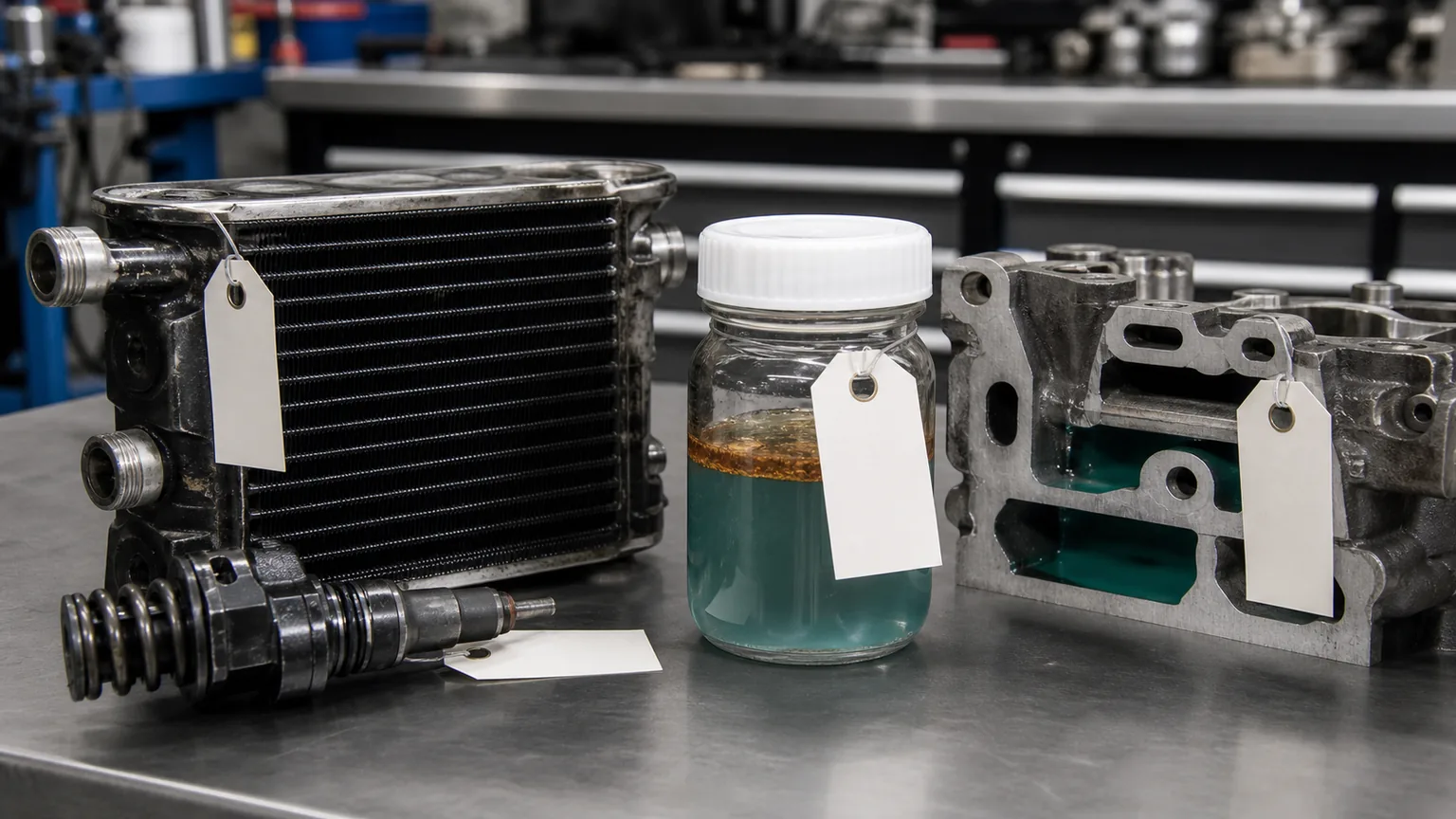
Preserve a labelled sample and circuit evidence without exposing personnel to a hot or contaminated system.
Confirm contamination without unsafe shortcuts
Possible clues include oily rainbow film, fuel-like liquid separation, unusual reservoir swelling, hose softening, coolant level rise and a reported diesel odour. None should be confirmed by tasting or close inhalation. Engine oil or transmission fluid can also form a film, so identify the contaminant with controlled sampling and, where necessary, laboratory analysis.
Use clean compatible containers, label vehicle/engine, date, sample point and operating state, and retain chain of custody. A sample from the reservoir may not represent fluid at a low drain. Record whether coolant was stirred, topped up or treated before sampling.
Map the engine architecture first
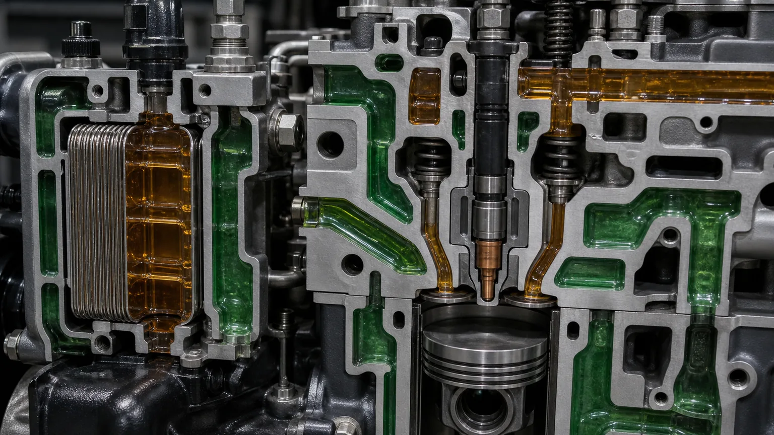
Obtain the engine model, serial/CPL or equivalent, vehicle/equipment configuration and current service diagram. Trace supply and return fuel, cylinder-head fuel galleries, injector cups/sleeves, coolant jackets, external fuel cooler and any ECM or aftertreatment fuel-cooling circuit. Do not transfer a known failure path from one diesel family to another.
The same vehicle model can use different engines, and a later production change can move the cooler or alter cup design. Confirm the suspected component’s OE number and coolant/fuel connections against the serial range.
Architecture determines which interfaces can physically allow fuel and coolant to meet.
Use pressure direction as a hypothesis
During running, some fuel circuits operate above coolant pressure, making fuel migration into coolant plausible at a shared boundary. After shutdown or cooling, pressure relationships can reverse or decay at different rates. High-pressure common-rail pressure does not necessarily act directly at every cooler or injector-cup interface.
Record when the coolant level rises or contamination appears: immediately at key-on pump operation, only after loaded running, during hot soak or after overnight cooling. This timing can prioritize tests but is not proof. Use application-specific pressure values and isolation methods.
Path 1: fuel cooler
A liquid-to-liquid fuel cooler can share a wall between diesel and engine coolant. A crack, braze defect, corrosion or seal failure can permit cross-flow. External dry appearance does not exclude an internal leak. Some vehicles also use air-to-fuel coolers that cannot create a direct fuel-to-coolant path, which is why architecture matters.
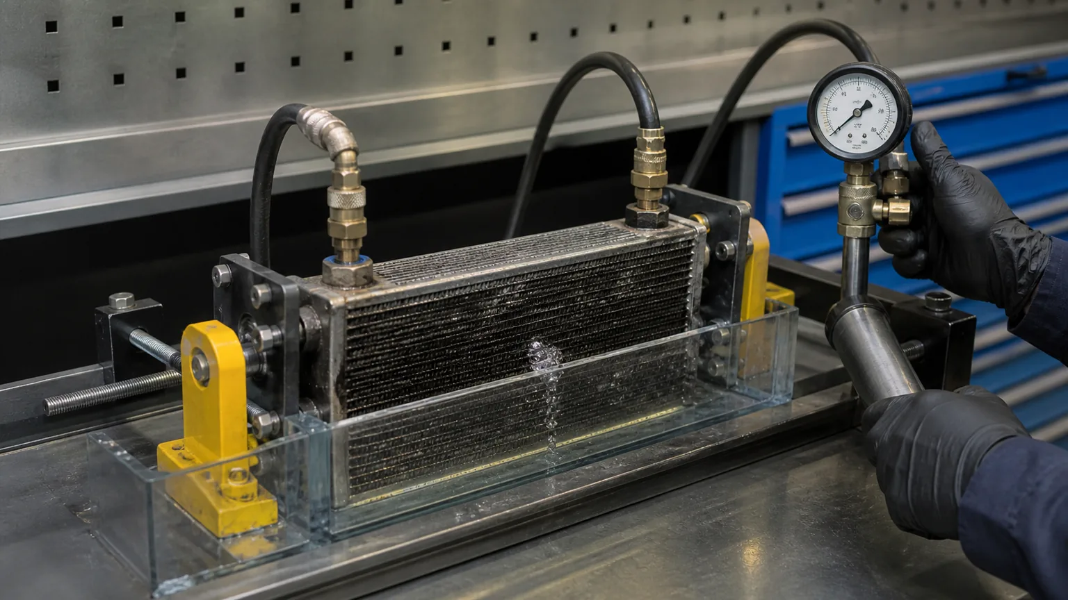
Where service information permits, isolate the removed cooler and test each circuit separately with the specified medium, pressure, temperature and hold time. Guard the component and account for test-tool leakage. Do not use oxygen, open flame or excessive shop air. Preserve port orientation and sample fluid before flushing.
Inspect mounting strain, freeze or impact damage, corrosion, wrong hoses and previous sealant. If a replacement cooler is required, compare circuits, ports, brackets and pressure ratings. Elecdura’s engine oil and fluid cooler programme illustrates the evidence needed for heat-exchanger matching, although fuel and oil coolers are not interchangeable.
Path 2: injector cup or sleeve
Some engines use injector cups or sleeves that separate fuel/injector regions from coolant. Cracks, corrosion, sealing damage, incorrect installation or cylinder-head condition can create a path. Other engines use different architecture, so an internet case for one make does not justify cup replacement on another.
Follow the engine maker’s diagnostic and removal procedure. Tests may involve controlled pressure, plugs, dyes or inspection tools specific to the head. Cup replacement can require dedicated pullers, cleaning, sealant, swaging or machining and injector-protrusion checks. Debris or incorrect installation can damage the head and fuel system.
Path 3: cylinder head or sealing interface
A casting crack, porosity, damaged bore, failed repair or application-specific gasket/interface may connect galleries. Combustion gas in coolant, compression loss or coolant in a cylinder is a different path that can coexist but does not by itself prove fuel contamination source.
Use the engine maker’s sequence after simpler accessible paths are evaluated. Head pressure testing, dimensional inspection and crack detection require a qualified shop and correct plugs/temperature conditions. Preserve failed cups, seals and cooler results so head removal is based on evidence.
Less common and misleading paths
Misrouted hoses after repair, a contaminated service container, incorrect fluid added to the reservoir, a shop transfer pump or a coolant/fuel heater unique to the application can mimic a component failure. Verify recent work and sample handling without assuming technician error. Engine oil or automatic-transmission fluid may be mistaken for diesel by appearance.
Check whether an auxiliary heater, fuel-conditioning module, marine system or equipment-specific thermal circuit uses coolant. Add every shared boundary to the diagram and test it in a logical order.
Test each circuit under the engine maker’s procedure and keep fuel, coolant and test equipment controlled.
Architecture-first decision sequence
Confirm the contaminant and preserve samples.
Identify engine serial and map every shared fuel/coolant boundary.
Record timing, pressures, level changes, faults and recent work.
Inspect and test the external fuel cooler where applicable.
Evaluate injector cups/sleeves only if the engine uses them.
Investigate cylinder-head or rarer paths using engine-specific tooling.
Repair the confirmed path and preserve the failed part.
Clean, replace affected materials and validate both circuits.
Differentiate diesel from engine oil and transmission fluid
Colour and surface film vary with coolant type, age and contamination level. Diesel may create a thin mobile layer and solvent-like effect, while lubricating oil can form heavier emulsion, but these observations are not conclusive. Heat, additives and prior stop-leak products change appearance. Do not diagnose by dipping a finger or igniting a sample.
Compare reservoir, radiator drain and engine-oil condition under the approved sampling plan. Check engine-oil level for unexplained rise or coolant signs and, where an integrated transmission cooler exists, inspect transmission fluid under the transmission maker’s procedure. A cooling system can have more than one contamination event, especially after repeated repairs.
A laboratory can use physical and chemical methods to distinguish fuel, engine oil, transmission fluid and coolant breakdown. Provide uncontaminated references of the actual fuel, engine oil, transmission fluid and new coolant when requested. Chain-of-custody labels should identify who collected and stored each sample and in what container.
Plan an isolated fuel-cooler test
Before removal, photograph every hose, clamp, bracket, flow arrow and part label. Confirm which connections carry fuel and coolant; colour or hose size alone can mislead. Drain into separate controlled containers so the first fluid from each circuit is not mixed. Cap open fuel and coolant lines against dirt and vapour release.
The test plan must specify whether the cooler is tested cold, warm or both, which side receives pressure, what fills the opposite side, allowable pressure, stabilization and hold time, leakage criterion and safety barrier. Tool fittings and plugs need ratings above the test condition and must not damage the production port. Account for gas compressibility and stored energy; a liquid test may be safer when prescribed.
An internal leak can be intermittent with temperature or pressure differential. A cold static pass does not always reproduce hot-soak distortion or cycling. If service information specifies a heated, vacuum, dye or pressure-cycle method, follow it. Do not increase pressure above the limit simply because the first test found nothing.
After testing, preserve the cooler without flushing when a supplier needs contamination or fracture analysis. Mark orientation and suspected area. If destructive sectioning is authorized, document pre-test condition and keep representative material. A replacement claim should connect the tested cooler’s number and lot to the engine, sample and worksheet.
Injector cup and sleeve evidence
When the engine uses cups or sleeves, record which cylinder locations are implicated by the approved test. Inspect removed cups and seals for cracks, corrosion, fretting, cutting, improper sealant, tool marks and seating damage. Keep positions separate; mixing all cups in one container destroys cylinder-level evidence.
Check the cylinder-head bore or seat with the engine maker’s gauges and method. Installing another cup into a damaged or incorrectly machined head can produce an immediate repeat. Verify injector condition, hold-down and protrusion requirements where relevant because the injector and combustion environment may affect the interface.
Installation cleanliness is critical. Protect fuel galleries and cylinders from chips, abrasive residue and coolant. Use only specified cups, seals, lubricant or sealant, tools, torque and curing time. Pressure-test the repair before completing assembly when the procedure allows, then retain measurements in the job record.
Cylinder-head decision criteria
Escalate toward head testing when external shared-boundary components pass approved tests, cup/sleeve evidence points to the head, contamination persists after controlled cleanup, or engine-specific service information identifies a casting or sealing path. Consider combustion-gas, compression, cylinder balance and coolant-pressure evidence as separate but related findings.
A machine shop should receive engine identification, suspected galleries, prior tests, overheat history and all removed parts. Agree test plugs, pressure, temperature, crack-detection method, flatness and repair limits. A generic cold water test may not reproduce an application-specific hot crack. Confirm whether the engine maker permits repair or requires replacement.
Assess hoses, plastics and seals after fuel exposure
Diesel can change elastomer volume, hardness and strength depending on material, temperature and exposure duration. Inspect coolant hoses inside and out for swelling, softness, blistering, delamination, cracking and loose reinforcement. Check reservoir, cap seals, thermostat seals, pump seals, heater hoses, O-rings and quick-connects. Follow manufacturer replacement guidance rather than assuming a washed part is sound.
Softened hoses can collapse under suction or slip from necks after the immediate leak is repaired. Fuel film can remain in an expansion tank’s seams and return later, creating a false recurrence. Replacement of heavily contaminated inexpensive plastic and rubber parts may be more controllable than repeated cleaning, but the decision must respect material and OEM guidance.
Design a documented flushing plan
List every branch to be flushed or replaced: engine block, radiator, heater core, reservoir, auxiliary heater, EGR or fuel cooler circuits where connected, hoses and low drains. Identify thermostats and valves that can trap fluid. Some components should be removed or replaced rather than exposed to cleaner.
Define cleaner, concentration, temperature, circulation time, rinse-water quality, number of cycles and final acceptance based on the official procedure. Capture waste in labelled containers. Do not mix fuel-contaminated coolant with ordinary drain water or discharge it to the ground. Record quantities removed and installed so unexplained retained volume is investigated.
After the final rinse, install new specified coolant at the correct concentration and bleed air. Establish a clean baseline sample and photograph the reservoir under consistent lighting. A residual sheen immediately after service should be evaluated against the documented process rather than prompting unplanned parts replacement.
Distributor claim triage
A returned fuel cooler should be quarantined, capped and labelled as contaminated. Confirm application, serial range, part number, lot, installation date and circuit connections before cleaning. Record whether the claim states fuel-to-coolant, coolant-to-fuel or external leakage and which tests support it.
Classify wrong application, port/hose misconnection, external damage, contamination before installation, no fault found, internal leak confirmed and analysis required separately. Commercial credit does not itself prove a manufacturing defect. Compare repeated claims by lot, engine platform and installer and retain both failed and unaffected samples if a pattern develops.
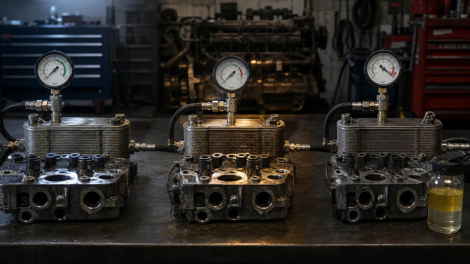
Timing and pressure state prioritize tests but do not replace component isolation and application data.
Cleanup after the repair
Removing the leak source does not make contaminated coolant serviceable. Follow the engine/vehicle maker’s flushing procedure, using approved cleaner and water quality, and protect the environment. Some hoses, seals, reservoir, cap, thermostat or heater components may require replacement after fuel exposure; inspect material condition and follow supplier guidance.
Multiple controlled flush cycles may be required, but aggressive household detergent or solvent can damage materials and leave residue. Do not circulate contamination through a new radiator or heater core. Dispose of fuel-coolant mixtures as regulated waste and keep a post-flush sample.
Validate the repair
Pressure- or leak-test the repaired component/system under the engine procedure, then refill with specified coolant and bleed correctly. Verify fuel-system integrity and prime as instructed. Run from cold while monitoring coolant and fuel levels, pressure, temperature, faults and leaks; then test under a representative load.
After full cool-down, recheck reservoir film, coolant concentration, hose condition and levels. Repeat sampling after the specified service interval because residual film can confuse an immediate visual check. Define the acceptance criteria before returning the vehicle.
Assign ownership of the follow-up check
Before returning the machine, name who will perform the follow-up inspection, where the retained baseline sample is stored and which observations require the case to be reopened. Keep the initial symptom, confirmed leak path, replaced components and cleanup result as separate entries. A completed parts order is not the same as a completed contamination investigation.
Give the next service team the sampling location and the engine maker's required follow-up conditions. Compare new observations with the documented post-cleaning baseline rather than with memory of the original reservoir appearance. Retain disputed components until the agreed supplier examination or case disposition is complete.
Warranty evidence and traceability
Record engine model/serial, vehicle/equipment details, hours/mileage, OE and supplier part numbers, lot/serial, install and failure dates, coolant/fuel types, recent work, symptom timeline, faults, level and pressure data, diagrams, sample labels and all isolated tests. Photograph ports, connections, mounts and the exact failed interface.
Keep the suspected cooler, cups/sleeves, seals and samples capped and labelled until disposition. Use Elecdura’s cooling-parts traceability process and DTC warranty data sheet to separate circuit evidence, root cause and replaced parts.
Traceable samples, engine-specific tests and post-cleaning records support a defensible repair and claim.
Frequently asked questions
Does fuel in coolant always mean a failed fuel cooler?
No. The engine may use injector cups/sleeves or other shared boundaries, and some fuel coolers are air-to-liquid with no coolant interface.
Can I keep driving if the engine temperature is normal?
No. Cross-contamination can damage hoses, seals, cooling and fuel systems and create safety risks even before temperature rises.
Can smell identify diesel?
Odour may be a clue but deliberate inhalation is unsafe and not definitive. Use controlled sampling and appropriate analysis.
Should the radiator be replaced automatically?
Not automatically. Inspect material compatibility, contamination and internal condition and follow the vehicle/radiator supplier’s cleanup or replacement guidance.
Why does fuel return after the cooler was replaced?
The original diagnosis may have missed another path, residual contamination may remain, or the repair/part may not be correct. Re-map and test the architecture.
Prove the path before replacing parts
Fuel-cooler, injector-cup and cylinder-head failures can produce a similar reservoir symptom. Engine-specific architecture, pressure state, controlled isolation and preserved samples distinguish them.
Send Elecdura the engine identity, diagrams, test results, photos, samples and part numbers. We can evaluate the heat-exchanger match and organize evidence for a traceable replacement programme.