You are here:Home » Resources » Blog » Industry Insights » Integrated EV Thermal Management Module vs Separate Loops: What Aftermarket Buyers Must Identify
Integrated EV Thermal Management Module vs Separate Loops: What Aftermarket Buyers Must Identify
Views: 0 Author: Elecdura Publish Time: 2026-08-31 Origin: Site
An “integrated EV thermal management module” is not a universal replacement part. Depending on the vehicle, one housing may contain an electric compressor, refrigerant valve block, chiller, water-cooled condenser, coolant manifold, pumps, sensors, and an internal heat exchanger. Another module with similar ports and dimensions may route refrigerant and coolant differently or communicate through a different electronic interface. Before quoting a module or one of its internal parts, identify the vehicle version, OE number, refrigerant, voltage, every fluid port, every connector, and the service boundary defined by the vehicle maker.
Integration is growing because EVs need to manage cabin, battery, power-electronics, motor, and charging heat with limited energy. Combining functions can reduce hoses, joints, refrigerant charge, weight, packaging space, and assembly work. Those vehicle-level advantages do not automatically make aftermarket identification easier. In fact, a single wrong assumption can turn a valve, chiller, pump, or electric A/C compressor order into an expensive module mismatch.
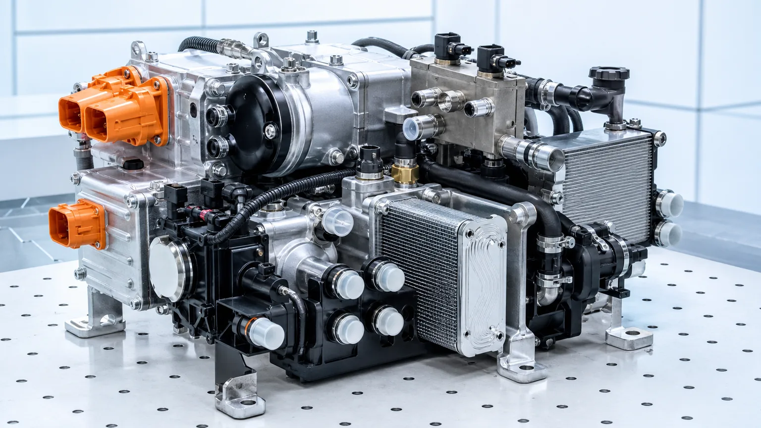
A compact housing can combine several thermal functions, so the module must be identified as a circuit rather than by silhouette.
What “integrated” can mean
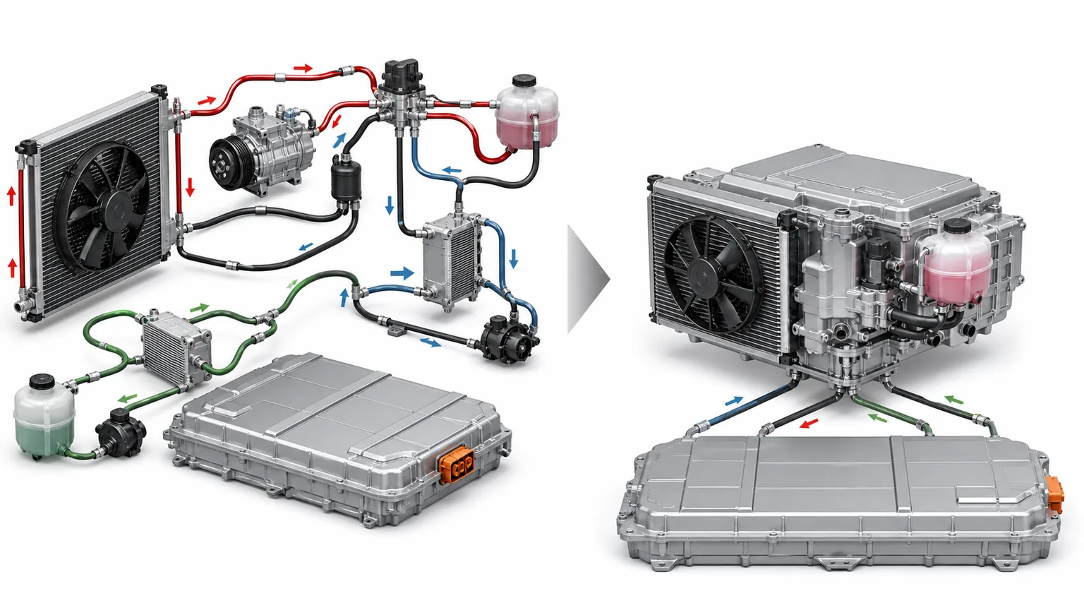
At one end of the design spectrum, an EV can use largely separate components connected by visible pipes and hoses: an electric compressor, front condenser, cabin evaporator, battery chiller, coolant pumps, multi-way valves, radiators, reservoirs, and control sensors. A technician can often trace the circuits component by component. At the other end, several refrigerant and coolant functions can be attached to a common manifold, built into a compact module, or supplied as one calibrated assembly.
Current integrated thermal modules may combine an electric compressor, expansion-valve block, water-cooled condenser, internal heat exchanger, chiller, refrigerant lines, and pressure and temperature sensors. This arrangement shows how much hardware can be packaged together, but it is not a template for every vehicle. Some modules add coolant pumps or reservoirs; some locate the compressor separately; some use a front air-cooled condenser; and some make selected valves or sensors replaceable while others are serviced only as a module.
Architecture
Typical identification advantage
Typical aftermarket risk
Separate components and loops
Individual parts, lines, and flow paths are easier to see and measure.
A shared symptom may still be caused by another component or control in the loop.
Common manifold with separate service parts
Labels and ports may remain accessible; selected pumps, valves, or sensors may have individual numbers.
Visual similarity can hide internal drilling, valve calibration, flow direction, or revision changes.
Highly integrated thermal module
One OE assembly number can define a complete tested unit.
The expensive module may be ordered unnecessarily, or a non-serviceable internal part may be offered without application approval.
The circuits that may meet inside one module
The first step in identification is to name each connected circuit. Never assume two similar hose nipples carry the same fluid or can be swapped.
Refrigerant circuit
The refrigerant side may include the compressor, pressure and temperature sensors, a valve block, a water-cooled condenser, a chiller, an accumulator or receiver function, and internal pipes. The architecture can reverse or redirect flow between cooling and heating modes. Port location alone does not tell you whether a connection is high side, low side, upstream of a valve, or part of a heat-recovery route.
Battery coolant circuit
The battery loop typically controls cell temperature for performance, charging, life, and safety. It may exchange heat with refrigerant through a chiller and with ambient air through a low-temperature radiator. A multi-way valve can bypass, combine, or isolate paths. Coolant chemistry, cleanliness, pump direction, and de-aeration requirements are application-specific.
Power-electronics and drive-unit circuit
Motor, inverter, onboard charger, and DC/DC converter heat can feed a shared low-temperature circuit or be divided across loops. Some vehicles recover this heat for cabin or battery warming. A replacement manifold or valve must therefore preserve internal passages and flow relationships, not merely accept the hoses.
Cabin heating and cooling
Cabin conditioning may use a refrigerant evaporator, refrigerant condenser, coolant heater core, PTC heater, or a combination. The module can change which heat source and sink is available in each mode. Elecdura’s comparison of EV battery chillers, condensers, and radiators helps distinguish the visible heat exchangers; an integrated module adds the challenge of hidden internal routing.
Integration reduces external connections, but the buyer still needs to identify every refrigerant, coolant, and electrical interface.
Why a similar housing can be the wrong part
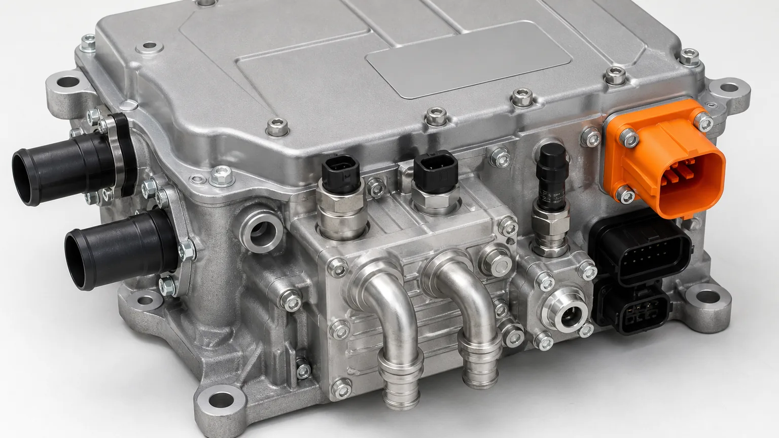
Suppliers and workshops sometimes receive a photograph showing a compact aluminum assembly with several hose ports and connectors. Two units may appear identical from one angle. The hidden differences can include:
internal coolant drilling and manifold routing;
valve spool or poppet arrangement and default position;
number, size, and plate pattern of internal heat exchangers;
refrigerant type and pressure class;
pressure-sensor range and temperature-sensor curve;
pump capacity, direction, voltage, and communication;
compressor voltage, power, insulation, and software;
connector keying, pinout, CAN/LIN/PWM or other control strategy;
bracket height and line-clearance details;
hardware or software revision associated with a production change.
That is why the OE number and supersession chain are essential. Dimensions can confirm that the supplied part agrees with the verified reference, but dimensions should not be used to invent a cross-reference. If the module carries more than one label, record all of them. A subcomponent label may identify its manufacturer while the assembly label identifies the vehicle-specific configuration.
Determine the service boundary before ordering
A visible sensor or valve is not automatically a separately serviceable part. Vehicle makers choose service boundaries based on sealing, calibration, cleanliness, electrical safety, production design, and validation. A catalogue may list a complete module even though the workshop would prefer to replace only a pump. Conversely, an OE procedure may allow replacement of a named valve, sensor, actuator, or compressor while retaining the manifold.
Use this sequence:
Read the vehicle service procedure. Identify whether the faulted item has an individual part number and approved replacement method.
Check the parts catalogue by VIN. Confirm module number, subcomponent number, required seals, fasteners, brackets, and one-time-use parts.
Review calibration or programming requirements. A valve or pump may need an initialization, bleed routine, software update, or learned-position procedure.
Confirm cleanliness and opening limits. Refrigerant and coolant paths may require immediate capping and controlled handling.
Check the warranty rule. Unauthorized disassembly can make the returned module impossible to analyze.
If no approved service path exists, offering a visually similar internal component may transfer unacceptable fitment and safety risk to the distributor. The correct response is to quote the verified module or request better application data—not to promise an unvalidated repair.
The evidence pack an aftermarket buyer should request
Vehicle evidence
VIN or chassis number and destination market;
model, production date, battery/drive variant, and thermal option where available;
refrigerant label and specified charge;
coolant specification for each connected loop;
diagnostic codes and freeze-frame data before parts are cleared.
Module identity
complete assembly OE number with suffix;
manufacturer number, serial number, QR/barcode, hardware and software revisions;
wide installed photographs from multiple directions;
close-ups of every label, connector, port, sensor, valve, cap, and bracket;
notes showing which hose or pipe was connected to each port.
Physical interfaces
overall envelope and mounting dimensions;
port outside diameter, sealing face, retention method, and orientation;
connector keying, pin count, latch position, and wire-side photograph;
clearance to adjacent body, battery, suspension, and underbody shields;
orientation arrows or flow markings where present.
A structured request is faster than a long message with no measurements. Elecdura’s cooling-system RFQ template can be adapted to collect these fields before a supplier begins cross-referencing.
Photograph ports straight on and in relation to the complete module; isolated close-ups without orientation are easy to misread.
How to trace a module without guessing
A useful circuit map begins with the installed vehicle. Mark the hose or pipe at both ends before disconnection according to the service procedure. Record fluid type, direction if known, connected component, and port label. Do not blow shop air through an unknown refrigerant or coolant passage. Do not use water to “see where it comes out.” Moisture, particles, excessive pressure, and valve movement can damage the assembly or destroy evidence.
If the service information includes a hydraulic or refrigerant diagram, compare it with the physical ports. Trace the battery coolant hoses to the battery loop, the low-temperature radiator, and the pump. Trace power-electronics hoses separately. Follow refrigerant pipes to the cabin unit, front heat exchanger, accumulator, or service ports. The purpose is to confirm the vehicle configuration, not reverse-engineer proprietary internal passages.
Labels such as IN, OUT, CHILLER, COND, BAT, MOT, or arrows can help, but translated catalogues may rename functions. Preserve the original markings in photographs. When creating product data, describe the physical interface and verified application rather than inventing a universal port name.
Failure symptoms do not identify the failed subcomponent
Poor cabin heat, slow battery conditioning, fast-charge derating, compressor shutdown, or a thermal-control code can originate inside or outside the integrated module. A restricted external radiator, low coolant, trapped air, contaminated refrigerant circuit, damaged harness, weak pump supply, software issue, or incorrect sensor input may cause similar symptoms.
Before ordering a module, the workshop should follow application service diagnostics and record evidence. Useful records include coolant level and condition, vacuum-fill or bleed results, pump command and feedback, measured flow or temperature difference where specified, refrigerant pressure and temperature under defined conditions, compressor insulation results, valve commands, sensor plausibility, supply voltage under load, communication status, and visual leak evidence.
This protects the replacement. Installing a new module into a contaminated refrigerant loop, mixed coolant, obstructed cooler stack, or unresolved electrical fault can damage it and make a warranty claim difficult to distinguish from a product defect.
Incoming inspection of an integrated module
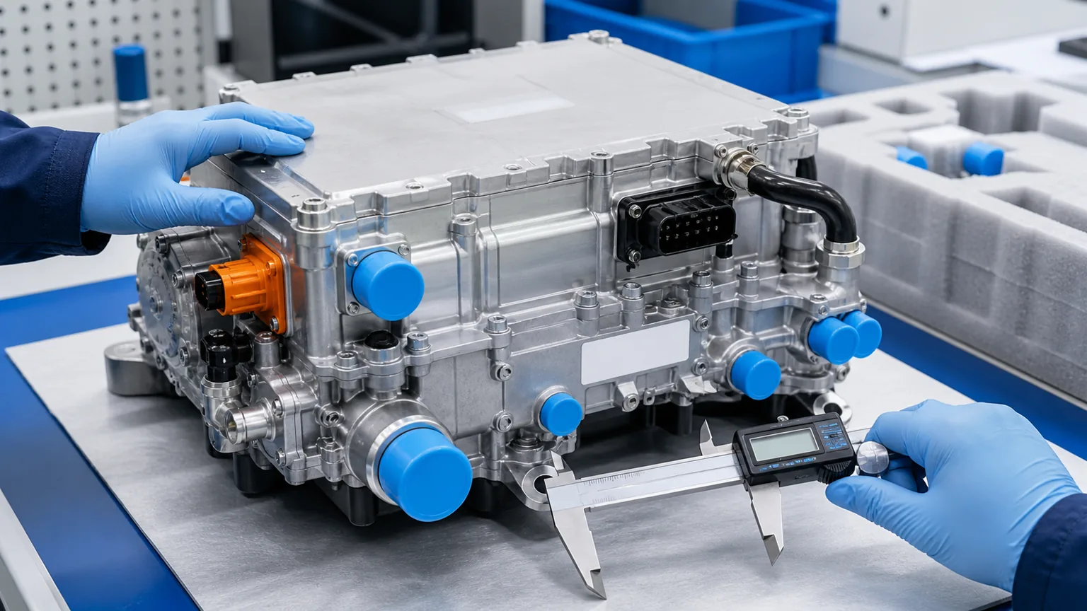
The highest-value incoming check is comparison with an approved golden sample and verified drawing. The inspection should not open sealed circuits or energize high-voltage equipment without a documented fixture and procedure.
Any sealed path has been open or contains visible residue.
Handling
Orientation, package supports, shock indicators if specified
The module moved in the box, ports carried load, or impact damage is present.
Test records
Leak/pressure/electrical tests appropriate to the part and batch
Required records are absent or cannot be traced to the serial/lot.
Leak testing must use the agreed medium, fixture, pressure, dwell, temperature, and acceptance limit for each circuit. A refrigerant-side test is not automatically appropriate for a coolant passage, and a generic bubble test cannot replace an application requirement. Electrical checks on compressors, pumps, valves, and sensors likewise need documented pinout and safe test conditions.
Incoming inspection should confirm identity, interfaces, cleanliness, and traceability without breaking sealed circuits.
Packaging is part of functional quality
An integrated module concentrates value and vulnerable interfaces in one package. Heavy compressor mass can load a manifold during a drop. Exposed plastic ports can crack. Connector latches can break against the carton. Uncapped refrigerant or coolant openings can admit moisture and debris. A package should support the assembly at structural points, prevent movement, isolate protruding ports, and keep identification visible.
For export or bulk supply, specify individual protective caps, clean bags where required, molded or engineered supports, moisture protection, carton orientation, stacking limits, drop/vibration validation, and a barcode that links the package to the module serial or lot. If a returned module arrives uncapped and wet, the return process should record that condition before further handling.
When separate components remain the better aftermarket option
Integration is not automatically superior for every replacement decision. A separate pump, valve, sensor, compressor, chiller, or heat exchanger can reduce repair cost when the vehicle maker supports individual service and the failure is confirmed. It can also simplify inventory when one standardized part fits multiple modules with a verified OE interchange.
A complete module can be the better choice when internal contamination is present, sealed passages or multiple valves are affected, the assembly is calibrated as a unit, disassembly is not approved, or repeated labor makes partial repair uneconomical. The decision belongs to application service data and evidence, not a universal preference for cheaper subparts or more expensive assemblies.
Common purchasing mistakes
Ordering from a cropped photo. Hidden ports, labels, brackets, and connectors remain unknown.
Calling the module a “chiller.” The chiller may be only one internal function.
Assuming every visible pump or valve is serviceable. Check the OE service boundary first.
Matching hose diameters only. Internal routing, coolant loop, seal, retention, and flow direction can differ.
Ignoring revision suffixes. Software, sensor, valve, or connector changes may occur without obvious housing changes.
Testing unknown pins. Improvised power can damage communication electronics or high-voltage equipment.
Accepting open ports. Moisture and debris can compromise refrigerant and coolant circuits.
Replacing the module from a symptom alone. External circuits, wiring, controls, filling, and heat exchangers can create the same symptom.
RFQ checklist
Required field
What to send
Application
VIN/chassis, model, production date, drive/battery version, destination market
Thermal architecture
Refrigerant label, coolant specifications, service diagram or verified loop description
Assembly identity
OE number and suffix, manufacturer number, hardware/software revision, serial/lot
Ports
Wide and straight-on photos, connected hose/pipe, diameter, seal/retention, orientation
Electrical
Voltage, all connector faces and keying, pin count, harness-side photos
Physical fit
Overall and mounting dimensions, installed clearances, brackets and isolators
Service boundary
Complete module or approved subcomponent; required seals, fasteners, programming and bleed routine
Failure evidence
Codes/freeze frame, leak photos, pressure/temperature/flow/electrical test results
Is an integrated thermal module the same as a heat-pump compressor?
No. The compressor may be part of the module, attached to it, or completely separate. The module can include multiple refrigerant and coolant functions beyond compression.
Can a valve be replaced if it has its own manufacturer number?
Not necessarily. A supplier number identifies the component but does not prove that the vehicle maker authorizes individual replacement, that calibration is compatible, or that the sealed module can be opened safely. Verify the OE parts catalogue and service procedure.
Can port count identify the module?
No. Port count is one screening field. Internal routing, fluid type, seal, location, connector, valve strategy, revision, and application must also match.
Should every thermal fault lead to complete module replacement?
No. Diagnose external loops, filling/bleeding, wiring, sensors, controls, compressor, pumps, valves, and heat exchangers according to the application. Replace the confirmed service part or module specified by the approved repair path.
How should a returned module be handled?
Cap each opening immediately with clean appropriate closures, keep fluids separated, preserve labels and serials, record the as-received condition, include diagnostic and installation evidence, and do not disassemble the module unless the warranty process authorizes it. Traceability guidance is available in Elecdura’s cooling-parts warranty evidence guide.
Identify the circuit before you identify the part
Integrated EV thermal management improves vehicle packaging and energy use, but it removes many of the visual clues that parts buyers once relied on. The correct aftermarket method is to map the connected circuits, establish the OE service boundary, verify the complete part-number and revision chain, compare all ports and connectors, and protect sealed passages through transport and returns.
For a sourcing review, send Elecdura the VIN/application, refrigerant label, OE and manufacturer labels, module photographs from all sides, every port and connector, installed hose routing, physical dimensions, diagnostic evidence, required quantity, and destination. That evidence allows the team to determine whether the correct supply is a complete integrated module, an approved subcomponent, or another part elsewhere in the thermal system.