You are here:Home » Resources » Blog » Industry Insights » Radiator Electrolysis and Stray-Current Corrosion: Voltage Tests Before Warranty Replacement
Radiator Electrolysis and Stray-Current Corrosion: Voltage Tests Before Warranty Replacement
Views: 0 Author: Elecdura Publish Time: 2026-08-31 Origin: Site
Radiator electrolysis and stray-current corrosion should not be diagnosed from one universal coolant-voltage number. Published radiator guidance uses different thresholds—commonly around 0.10 V in some sources and 0.30 V in others—and readings change with meter setup, reference point, coolant temperature, engine state and electrical loads. Follow the vehicle or radiator supplier’s limit, document the complete test state, and isolate the circuit before blaming the radiator.
For a replacement or warranty review, send Elecdura the application and OE number, corrosion photographs, coolant history, meter/reference/probe details, readings in each operating state, ground-repair results and lot label through the wholesale radiator programme.
Electrolysis, stray current and chemical corrosion are not the same claim
“Electrolysis” is widely used in workshops for electrically influenced coolant corrosion, but the investigation should be more precise. Stray current can enter the coolant because electrical equipment seeks an unintended ground path. Galvanic effects involve dissimilar materials and electrolyte. Chemical corrosion can arise from depleted, incorrect, mixed or contaminated coolant, oxygen entry and poor maintenance. Erosion, cavitation, road salt and external impact can create similar pinholes.
A voltage reading is evidence about an electrical condition at that moment; it does not identify the exact damaged component or prove that every pinhole was caused by current. Combine electrical tests with coolant, grounding and physical-failure evidence.
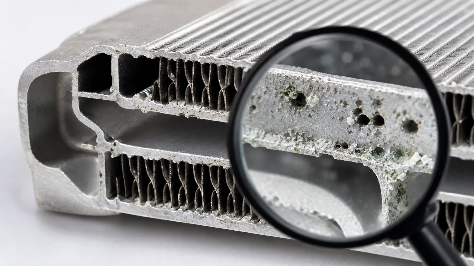
Pinhole appearance starts an investigation but does not establish a single cause by itself.
Safety and meter setup
Work only on a cooled system under the vehicle maker’s procedure. Never open a hot pressurized cap. Keep clothing, leads and hands away from belts, fans and high-voltage components; EV and hybrid cooling circuits require model-specific high-voltage safety.
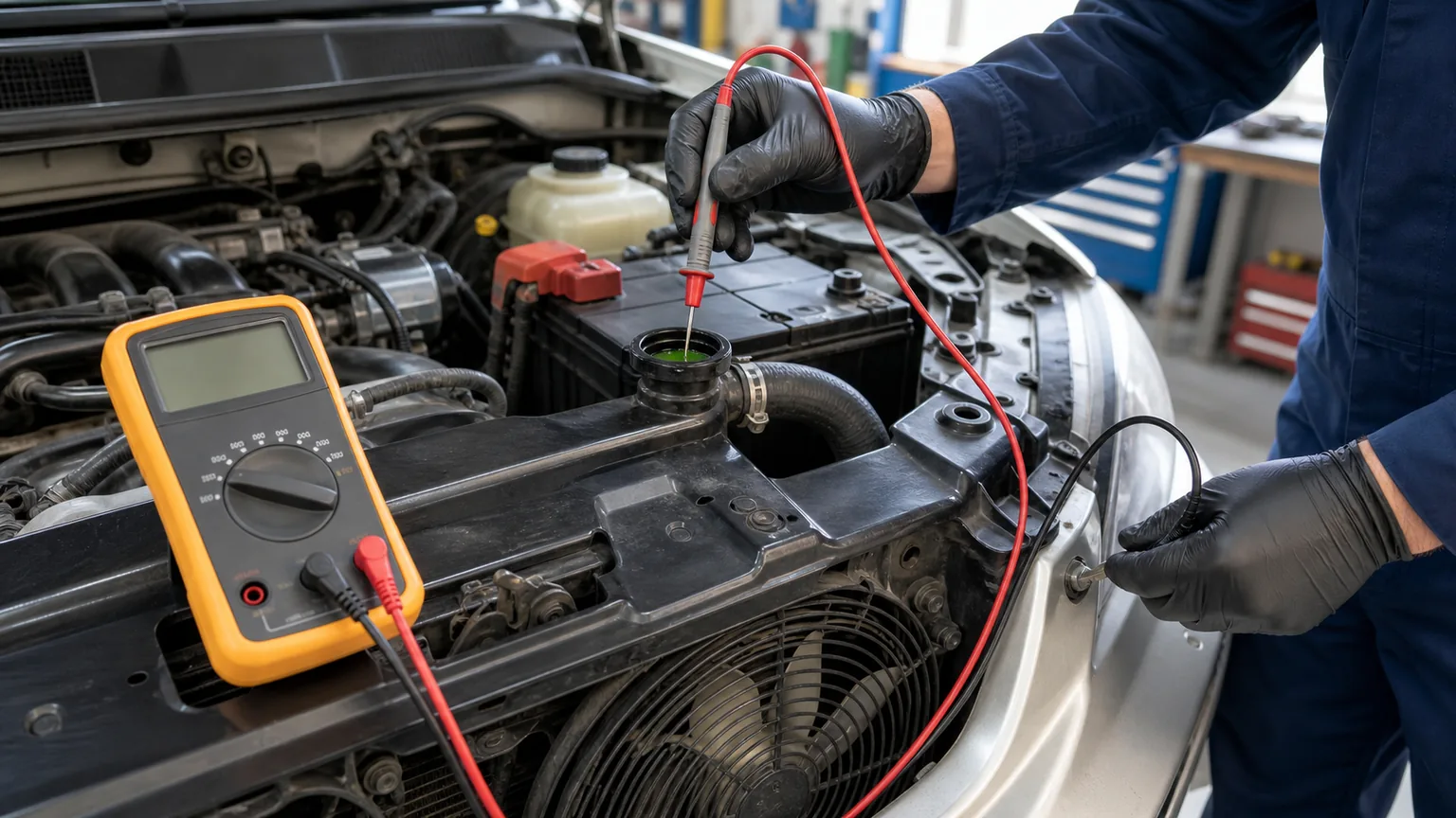
Use a known, high-impedance digital meter with suitable leads and record model, range and calibration status. Establish the specified reference—often battery negative or a defined engine/chassis point—and verify reference integrity. Place the coolant probe at the approved location without touching metal, tank walls or filler neck. Probe material, immersion depth and contamination can affect results.
Reference point, probe placement and test state must be recorded for a repeatable reading.
A repeatable multi-state test
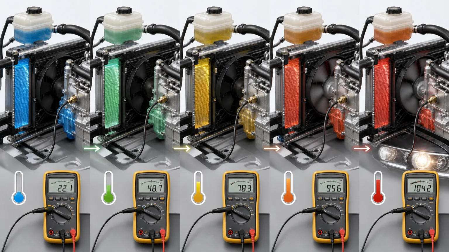
Record the vehicle, coolant temperature and meter baseline, then measure only in states permitted by service information: key off; key on/engine off; engine idling; and selected electrical loads one at a time. Loads may include blower, lighting, heated glass, A/C request, cooling fan and accessories. Note alternator charging state and engine speed. Do not disconnect safety-critical grounds or circuits while running.
A step change when one load activates can help locate a ground-path problem. A stable reading across states may point away from that load but does not automatically prove coolant chemistry is correct. Repeat measurements after corrective work using the same reference, probe location, temperature and state.
State-by-state changes are more useful than an isolated number with no operating context.
Why published voltage limits differ
Some radiator guidance treats readings above approximately 0.10 V as requiring attention; other guidance commonly cites approximately 0.30 V. These are not interchangeable universal laws. Differences can reflect the supplier’s product, vehicle population, test method, reference, probe material, meter and risk policy.
Use the limit supplied for the vehicle/radiator and reproduce its method. If none is available, report the measured values and state precisely rather than converting an internet threshold into a warranty verdict. A reading near any boundary should be repeated and investigated alongside voltage-drop and coolant tests.
Ground-path checks
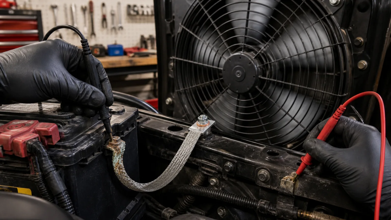
Inspect battery terminals, battery-to-engine and battery-to-chassis cables, engine-to-chassis straps, cab/body grounds and grounds for fans, alternator, starter, lights, winches, inverters and aftermarket accessories. Look for loose fasteners, paint under lugs, corrosion, broken strands, undersized cables, heat damage and a component grounded through a coolant hose or cooler stack.
Perform loaded voltage-drop tests under the maker’s procedure. Ohmmeter resistance on an unpowered cable can miss a poor joint that fails under current. Measure across the intended path while the relevant load operates, record polarity and value, and compare with application specifications. Repair the connection, do not merely add an undocumented ground that can create new current paths.
Loaded voltage-drop testing finds ground restrictions that a static continuity check can miss.
Alternator and accessory context
Charging-system faults, ripple and high-current accessories can influence electrical conditions, but alternator diagnosis requires the vehicle maker’s method and suitable instrument. Record charging voltage, load and any AC-ripple test correctly; do not infer a failed diode from an unsuitable meter reading alone.
Aftermarket audio, lighting, heaters, inverter, winch, liftgate or welding equipment deserves special attention. Trace its return path and installation date relative to the radiator failure. Cooling fans with damaged ground or controller wiring can create load-dependent changes near the heat-exchanger module.
Coolant chemistry and maintenance
Identify coolant specification, brand/type if known, concentration, age, top-up water and mixing history. Check for oil, fuel, combustion products, sealant, rust, scale and suspended solids. Use approved refractometer, strip or laboratory methods; colour alone does not prove chemistry.
Incorrect concentration, hard or conductive water, depleted inhibitors and mixed technologies can accelerate corrosion even after electrical grounds are repaired. Flush and refill only to the engine/vehicle maker procedure, including heater, auxiliary and low points. Dispose of coolant responsibly and keep samples if a claim depends on analysis.
Inspect the failure pattern
Photograph the radiator installed and removed, then map every leak. Examine internal and external tube surfaces, header joints, tanks, fittings, mounts and contact points. Electrical/chemical pinholes may be widespread or concentrated, but road impact, fin rub, fan contact, freeze expansion, vibration and manufacturing defects must remain in the differential diagnosis.
Do not clean aggressively or section the part before supplier authorization. Preserve deposits and coolant samples. A laboratory may use microscopy, elemental analysis or deposit/corrosion examination, but interpretation needs chain of custody and representative material.
Isolation sequence
Confirm safe meter setup and repeat baseline readings.
Record key/engine and individual-load states.
Inspect and load-test primary grounds.
Switch or isolate nonessential loads only under approved procedure.
Repair identified ground or wiring faults.
Repeat the identical coolant-voltage sequence.
Test coolant condition and investigate contamination.
Inspect radiator failure morphology and non-electrical causes.
Correct causes before installing the replacement.
Build a test sheet that another technician can repeat
A useful sheet begins with date, vehicle identification, odometer or hours, ambient temperature, coolant temperature, battery state and recent charging or jump-start events. List meter make/model, range, lead condition and verification check. Draw or photograph the negative-reference point and coolant-probe point so a second technician does not choose a different ground or immerse the probe at another location.
Create one row per state: key removed; key on/engine off; cranking only if the approved procedure calls for it; engine idle; raised engine speed; and each electrical load. Record DC voltage polarity and magnitude, load status, engine speed and charging voltage. If the procedure calls for AC/ripple evaluation, use a separate correctly configured measurement and label it clearly. Do not combine DC coolant voltage and AC charging-system results in one unlabeled column.
Wait the specified stabilization time and note fluctuations rather than selecting a convenient minimum. If fans cycle, record readings before, during and after the event. If the probe drifts or touches metal, invalidate that row and repeat it. Photograph the meter and state where safe, but keep a written value because reflections and auto-ranging symbols may be unreadable in an image.
After a ground or wiring repair, repeat the same sequence at a comparable coolant temperature. A before/after table is stronger than a claim that the reading “went down.” If the reading remains abnormal, continue the approved isolation; do not assume the new radiator itself will correct the circuit.
Use load changes to narrow the path
If coolant voltage rises when the cooling fan starts, inspect the fan motor or electronic fan, controller, connector, power supply and its ground path, as well as the engine/chassis bonds that should carry return current. Confirm whether the fan frame or shroud contacts the heat-exchanger stack. A failed ground may seek a path through brackets, coolant pipes or sensor grounds.
A change with the cabin blower, heated window, lighting or A/C request directs attention to those load circuits and common ground paths, but one correlation is not final proof. A/C request may simultaneously command fans and change idle/alternator output. Activate one load at a time where the vehicle allows it and use current diagrams to understand linked commands.
A change with engine speed can relate to alternator output, engine-ground voltage drop, vibration at an intermittent connection or an accessory that changes state. Record charging-system behaviour and load-test the intended return paths. Do not disconnect the alternator or battery on a running modern vehicle as a diagnostic shortcut.
If no load changes the reading but the supplier limit is exceeded, verify meter setup and reference, then investigate constant-current paths, coolant chemistry and conductive contamination. A stable low reading also does not clear an obviously corroded system; the damaging condition may have been intermittent or corrected before testing.
Separate internal from external corrosion
Internal corrosion begins on surfaces exposed to coolant and may leave deposits, thinning or perforation inside tubes, headers or fittings. External corrosion can be driven by road salt, coastal air, fertilizer, cleaning chemicals, trapped mud, dissimilar-metal contact and wet debris between stacked heat exchangers. A pinhole near an external contact patch should not be assigned to coolant electrolysis without examining the other side.
Map the distribution. Is damage confined to the lower road-facing area, beside a steel bracket, around one ground-carrying fitting, across many internal tube ends, or under a packed layer of dirt? Photograph neighbouring condenser and charge-air cooler surfaces and the frame. Cross-section or laboratory examination may show whether metal loss progressed from inside or outside, but destructive work must preserve chain of custody.
Cavitation or erosion-corrosion can create localized metal loss where fluid velocity, vibration or vapour formation acts on a surface. Incorrect pressure control, coolant level, pump condition and engine-specific liner/coolant requirements may matter. Do not label every smooth pit an electrical burn.
Coolant sampling without destroying evidence
Collect samples only from a cooled, depressurized system using clean compatible containers and the agreed location. Label vehicle, date, sample point, temperature state and whether the coolant was stirred, drained or taken from the reservoir. A reservoir sample may not represent sediment at the radiator bottom, and an open dirty drain pan invalidates laboratory conclusions.
Retain an unopened reference of new coolant if product quality or mixing is disputed, along with invoices and water-source information. Record every top-up and additive. Do not taste coolant, deliberately inhale vapour or touch contaminated fluid. Fuel, oil or combustion contamination requires its own safety and repair procedure.
Laboratory analysis can assess inhibitor condition, metals, contamination, pH and other properties when the method is appropriate. A single field conductivity or pH reading is useful screening but does not replace the coolant manufacturer’s specification. Interpret results with mileage/hours and maintenance history.
Special considerations for hybrids, EVs and multi-loop vehicles
Electrified vehicles may have separate engine, battery, inverter, motor, charge-system and cabin thermal loops using application-specific coolants and electric pumps or heaters. Never assume the conventional radiator test applies to a high-voltage component or open a circuit without the maker’s isolation and personal-protective-equipment procedure.
Identify which loop feeds the damaged heat exchanger and which electrical components contact it. High-voltage insulation monitoring and coolant requirements are specialized diagnostics. Keep low-voltage stray-current investigation separate from high-voltage insulation work and refer the latter to qualified personnel.
Claim triage for distributors
Quarantine the returned radiator and preserve labels, deposits, caps, plugs and packaging. Confirm application, install date, lot and claimed leak before cleaning. Ask whether ground and coolant tests were performed before the part was removed; post-removal readings on a changed circuit cannot reconstruct every operating condition.
Classify the initial case as confirmed leak pending cause, transit/impact, rub/contact, chemical contamination, electrical contribution suspected, installation/fitment, no fault found or manufacturing analysis required. Commercial goodwill can be recorded separately from technical cause. This avoids turning every credited radiator into a manufacturing-defect statistic.
When several failures share a lot, vehicle platform or customer, compare evidence using the same checklist. A lot-linked brazing pattern may require supplier containment; one fleet with abnormal grounds and mixed coolant may require site corrective action. Preserve enough parts from both failed and unaffected groups for meaningful comparison.
Record tests that do not reproduce the complaint
An unchanged reading after a selected load is switched on is still useful evidence when the reference points and test conditions are documented. Record the observation as no change under that condition, not as proof that every electrical path is sound. Keep negative findings alongside abnormal readings so the next technician knows which conditions were actually investigated.
If the original operating state cannot be recreated after removal or repair, state that limitation in the service record. Do not backfill a missing pre-repair value from a later measurement. A distributor can keep the failure cause unresolved while still processing an agreed commercial remedy.
Warranty evidence pack
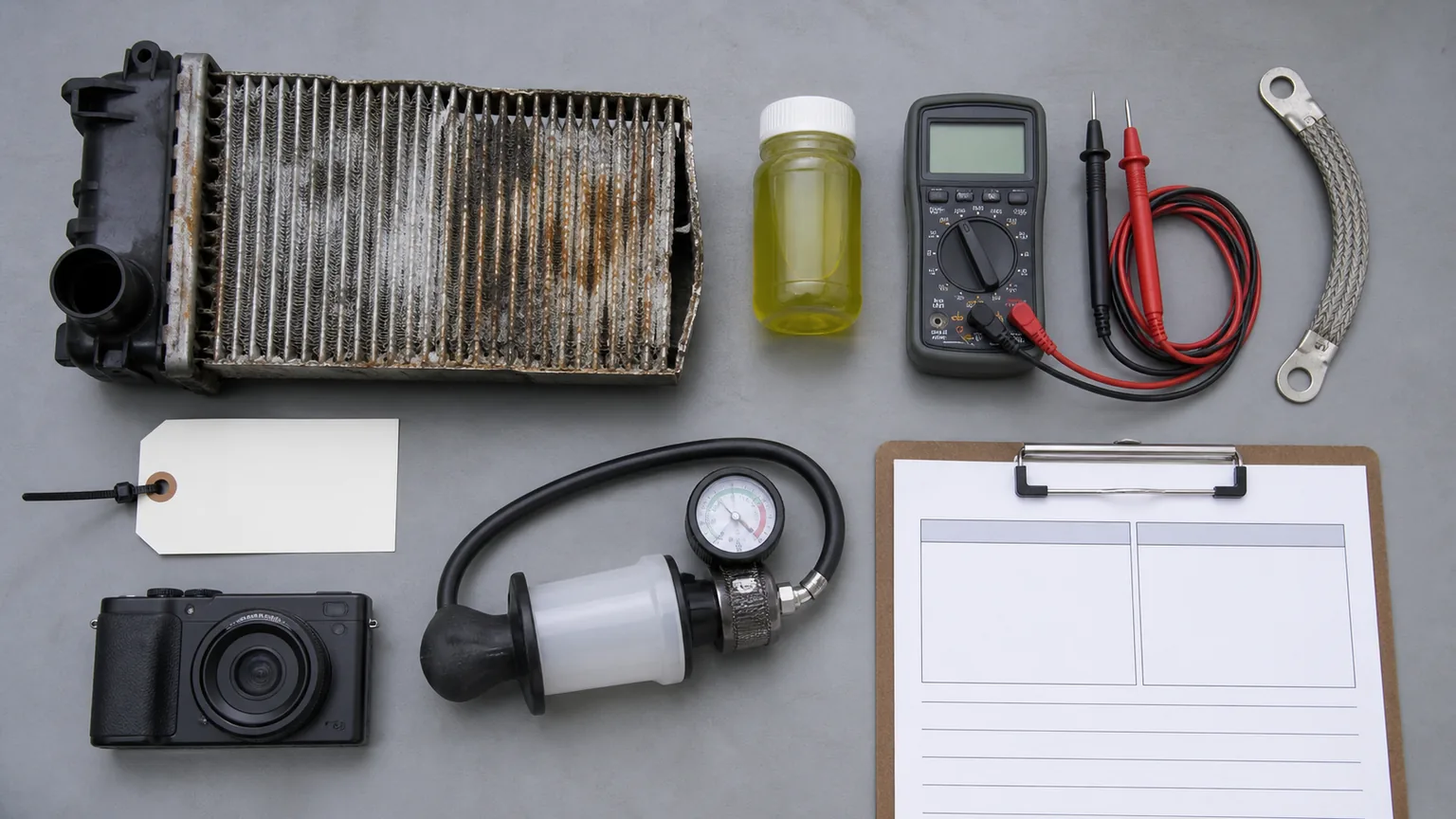
Include VIN/application, engine, radiator OE and supplier numbers, lot/serial, install date and hours/distance, coolant specification and service history, overheat or contamination events, accessory modifications and prior ground repairs. Add wide and macro corrosion photographs, leak locations, cap/system pressure evidence and packaging/install condition.
For every electrical reading, state meter, range, lead reference, probe location/material, coolant temperature, engine speed, ignition state and active loads. Include loaded voltage drops and readings before and after repair. Link evidence to the returned part using Elecdura’s cooling-parts traceability method.
A documented test method and before/after results make the warranty conclusion auditable.
Corrective action before replacement
Repair verified grounds and wiring, correct charging/accessory faults, restore specified coolant and eliminate contamination or combustion leakage. Inspect cap, mounts, isolators, hoses, fan clearance and cooler-stack contact. A new radiator should not be installed into the same electrical, chemical or mechanical fault.
After replacement, fill and bleed correctly, repeat the recorded electrical tests, verify temperature and fan operation, and recheck after the first duty cycle. Keep baseline readings for later comparison. Persistent bubbling or pressure requires its own diagnosis; Elecdura’s coolant bubbling guide separates normal return flow from air, boiling and combustion gas.
Supplier and fleet prevention
Suppliers should provide corrosion/material controls, coolant compatibility, leak and durability evidence, traceability and claim instructions. Fleets should maintain ground inspections, coolant testing, accessory-install standards and cleaning suited to heat, dust and salt exposure. Elecdura’s climate-resilient cooling guide helps connect environment to the parts programme.
Trend failures by vehicle, radiator lot, location, coolant, ground reading and duty. A cross-fleet lot pattern deserves supplier containment; repeated failures on one modified vehicle point toward the application.
Frequently asked questions
Is 0.10 V the universal maximum?
No. Published guidance differs. Use the application or radiator supplier’s limit and its exact procedure.
Is 0.30 V always acceptable?
No. It may exceed another supplier’s criterion and test state matters. Document and investigate rather than declaring pass/fail from a generic number.
Can I put the probe against the filler neck?
No if the procedure requires isolated coolant contact. Touching metal changes the circuit and can invalidate the reading.
Will replacing the ground strap stop existing leaks?
It can correct an electrical cause but cannot repair metal already perforated. Replace or professionally repair the damaged component as appropriate.
Does every pinhole mean electrolysis?
No. Chemical corrosion, erosion, impact, rub, cavitation and manufacturing causes must also be evaluated.
Make the voltage test reproducible
The strongest diagnosis is not the highest or lowest number; it is a repeatable sequence that shows how readings respond to operating states and corrective work, supported by coolant and physical evidence.
Keep the completed worksheet with the vehicle service record so future technicians can compare the same reference points and test states after electrical, coolant or accessory changes.
Send Elecdura the complete record and part details. We can assess replacement fit, preserve lot traceability and structure the supplier claim around evidence rather than a disputed universal threshold.