English
Views: 0 Author: Elecdura Publish Time: 2026-08-13 Origin: Site
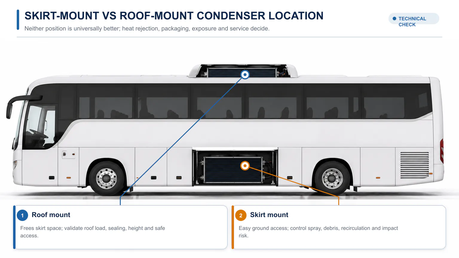
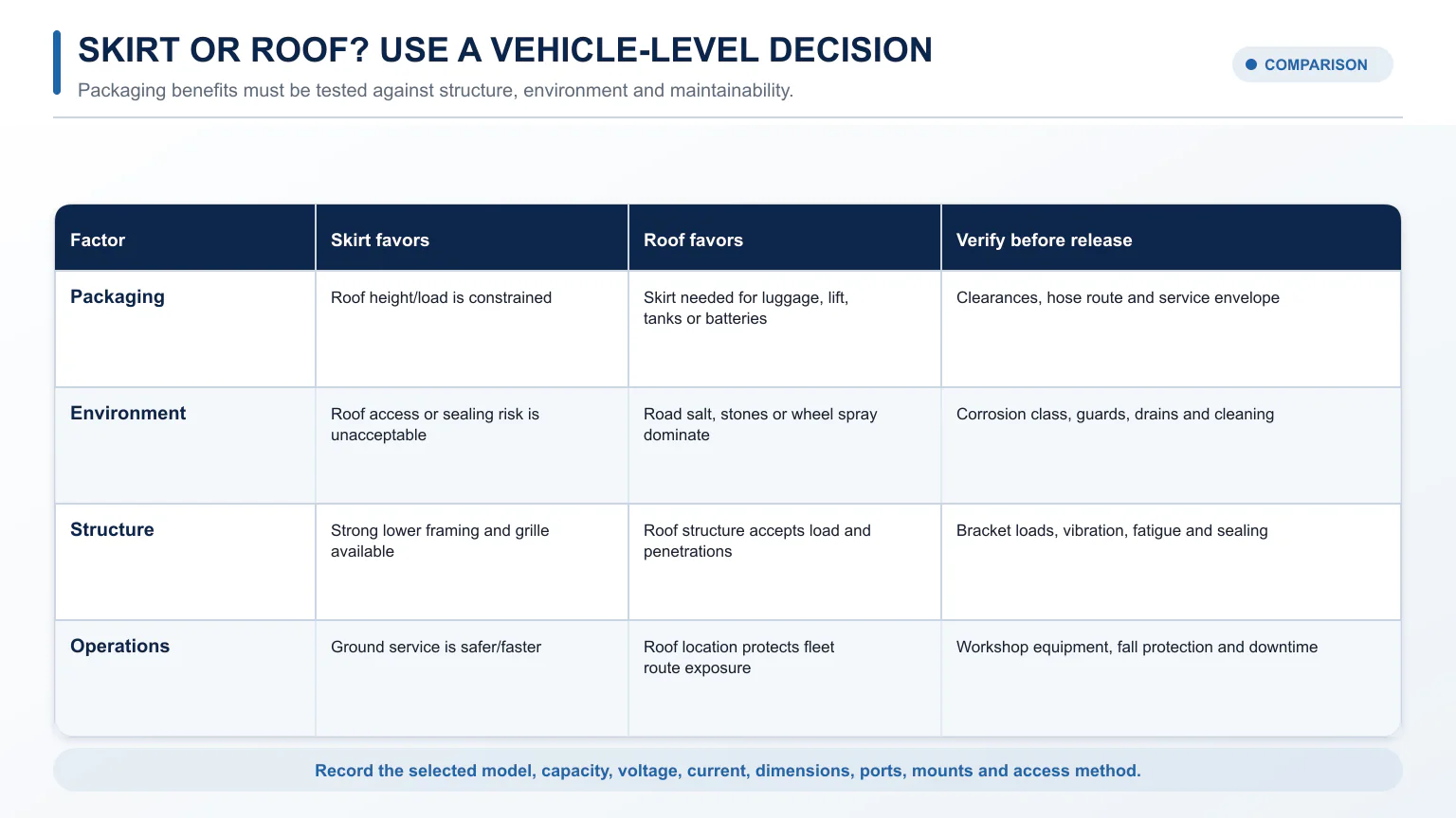
Neither mounting position is universally better. A skirt-mount condenser keeps weight and service work low on the vehicle and avoids roof penetrations, but it is exposed to road spray, salt, stones, mud, and hot-air recirculation under the body. A roof-mount condenser can free skirt space for luggage, lifts, tanks, or batteries and reduce wheel-spray exposure, but it adds roof loading, vehicle height, wind and sun exposure, sealing requirements, longer access paths, and rooftop service risk.
The correct choice is the position that provides verified heat rejection and airflow under the vehicle's worst operating conditions while meeting packaging, structural, electrical, hose-routing, corrosion, noise, and service constraints. Buyers can compare application-specific options in Elecdura's wholesale AC condenser range, but a condenser should not be selected by fan count or external dimensions alone.
Condenser location changes packaging, exposure, structure and service requirements.
Decision factor | Skirt mount | Roof mount |
|---|---|---|
Packaging | Uses lower body/skirt space | Frees skirt space but uses roof area |
Environmental exposure | Road spray, salt, mud, stones, wheel debris | Sun, rain, wind, branches, height impacts |
Airflow risk | Underbody hot-air recirculation and blockage | Roof turbulence, recirculation, nearby rooftop equipment |
Structure | Frame/skirt brackets and road vibration | Roof reinforcement, sealing, wind and dynamic loads |
Service access | Ground-level access, sometimes cramped/dirty | Open access possible but fall protection may be required |
Hose routing | Often closer to chassis components | Longer vertical/roof routes and body penetrations |
Typical fleet benefit | Low-height vehicles and easy exterior service | Buses needing skirt space or protection from road salt |
A condenser rejects heat from high-pressure refrigerant to outside air. A “skirt condenser” is normally a coil, fan, shroud, and protective assembly mounted along the lower side of a bus or heavy vehicle. A “roof condenser” places that heat-rejection assembly on the roof. Some products combine condenser, compressor, evaporator, heating, or ventilation into a complete rooftop HVAC unit. Those complete systems should not be compared directly with a bare remote condenser without separating functions and test conditions.
Mobile Climate Control installation documentation says bus condensers are normally located in the skirt or on the roof and emphasizes free airflow, protection, mounting, and voltage. Bergstrom publishes skirt and rooftop condenser assemblies with different capacities and dimensions. These examples show that position is one design variable, not a capacity class.
Both locations need an unrestricted inlet, a sealed path through the coil and a clean discharge route.
The condenser must reject cabin heat plus compressor work. Its ability depends on refrigerant mass flow, condensing temperature/pressure, ambient air temperature, air mass flow, coil condition, fin/tube design, and how hot discharge air leaves the vehicle. A large coil with poor airflow can perform worse than a smaller correctly ducted unit.
Compare capacity only when rating conditions are known. A published BTU/h or kW value may assume a particular refrigerant, condensing temperature, air inlet temperature, airflow, fan voltage, and clean coil. Ask for the test point or selection calculation. Do not add fan nameplate airflow values and assume that amount passes through an installed coil; guards, shrouds, static pressure, voltage drop, and recirculation change performance.
Air must enter the coil from the intended side and leave without returning to the inlet. Recirculation raises entering-air temperature, which raises head pressure and compressor load. It can create a system that cools acceptably on a workshop test but trips on a hot, stationary, fully loaded bus.
Technicians may access a skirt unit from ground level or a low platform. Fans, screens, coils, receivers, and hose connections can be inspected without climbing onto the roof. This can reduce routine service time if doors and guards are designed well.
A skirt condenser avoids cutting and sealing the roof for the condenser assembly and keeps roof space available for emergency hatches, solar panels, antennas, HVAC evaporators, or other equipment. It also avoids adding condenser mass at the highest point of the vehicle.
On some layouts, a skirt condenser is closer to an engine-driven compressor, receiver-drier, or other chassis components. Shorter routing can reduce hose material and joints. This is an application benefit, not a rule; rear-engine buses and distributed HVAC layouts vary.
Wheel spray carries water, road salt, mud, sand, and stones. MCC recommends protecting a skirt condenser near a wheel with a splash guard. The guard must protect the coil without restricting inlet or discharge airflow. Material, coating, fasteners, electrical connectors, and fan motors should match the corrosion exposure.
MCC's service documentation recommends mounting the skirt condenser close to the skirt and using skirting when the gap would permit recirculation. The exact installation should follow the product manual. Avoid hot engine, exhaust, brake, or road air entering the coil. Provide a clean discharge path away from the inlet.
Chassis rails, body panels, luggage structures, and screens can block air. MCC warns that restricted airflow raises system pressure and can reduce cooling or damage the compressor. Cutting a skirt opening or removing a support also affects body structure; brackets and reinforcement must be engineered rather than improvised.
Curbs, road debris, ramps, and lifting equipment can damage a low unit. Confirm approach/departure and breakover conditions, suspension travel, tire failure envelope, jacking points, and workshop lift contact. Use guards and placement that protect the coil without trapping dirt.
Mobile Climate Control's CR-410 roof condenser literature highlights freed skirt space for options such as CNG tanks, wheelchair lifts, and luggage compartments. Electric buses may also need lower-body space for batteries or power electronics. Moving the condenser upward can solve a whole-vehicle packaging conflict.
A roof condenser avoids direct wheel spray and many stone impacts. MCC describes roof mounting as a solution to road-salt damage in relevant bus applications. It is still exposed to moisture, salt air, ultraviolet radiation, tree debris, and wash chemicals, so corrosion and sealing remain design requirements.
A clear roof location can provide access to outside air away from engine and road heat. Fan-forced airflow remains essential at low speed and idle. Roof boundary-layer flow and nearby equipment can either help or disrupt the fans, so the installed configuration must be validated.
The roof must support unit mass plus vibration, braking, cornering, road shock, wind, maintenance loads, and any code-specific requirements. Use designed rails, backing, reinforcement, isolation, and fasteners. A thin roof skin is not a structural mounting surface.
MCC documentation warns that roof alterations require the supplied sealing procedure to prevent water entry. Control every penetration for mounts, hoses, wiring, and drains. Sealant choice, surface preparation, fastener torque, joint movement, and inspection access matter. Plan how a future replacement will be resealed.
Check legal and route height, depots, wash bays, bridges, trees, doors, and maintenance facilities. Include protective covers in the final height. Rooftop aerodynamic drag and wind noise may matter on highway duty.
Roof access may require a platform, fall protection, lockout, and safe lifting equipment. Design service panels so technicians do not lean over running fans or damage fins. Consider whether a failed fan can be replaced without removing the complete unit.
Roof mounting often increases the length and elevation change of the discharge and liquid lines connected to the condenser. Longer lines add internal volume, pressure drop, joints, weight, and potential leakage. They can affect refrigerant charge and oil distribution, but longer routing does not automatically make a system unreliable. The system designer must size the affected discharge and liquid lines for refrigerant, capacity, equivalent length, elevation, pressure drop, velocity, oil management, and allowable charge.
Use the hose and fitting system approved for the refrigerant and vehicle environment. Support lines to prevent abrasion and fatigue, keep them away from exhaust and sharp edges, provide movement loops where body/engine motion requires them, and protect roof/body penetrations. Do not create low points or traps contrary to the system design.
After changing condenser location or hose length, calculate and validate refrigerant and oil balance. A charge quantity from the donor vehicle may no longer be correct. Use pressure, temperature, subcooling or other manufacturer-specified commissioning measures under controlled conditions.
Condenser fans are high-current loads. Confirm 12 or 24 V architecture, total current at rated voltage and temperature, startup/transient current, wire size, fuse/breaker, relays or electronic control, ground path, connector environmental rating, and alternator or battery capacity. MCC notes that low voltage can slow fans and lead to pressure buildup.
Variable fan control can reduce noise and power when full airflow is unnecessary, but it must maintain refrigerant pressure within safe limits and respond to sensor or communication faults. Define whether fans are staged, PWM controlled, or networked and whether speed feedback exists. Place temperature and pressure sensing according to the HVAC design.
Noise includes fan blade tone, motor, airflow turbulence, grille/guard interaction, vibration into body panels, and rooftop structure radiation. A fan's free-air sound number may not predict installed bus noise. Validate at operating speeds and passenger/driver locations.
The final location should be selected at vehicle level rather than by condenser capacity alone.
Define the thermal duty: cabin load, operating ambient, occupancy, glazing, door cycles, compressor, refrigerant, and duty.
Map packaging: skirt equipment, roof equipment, structure, height, access, and hose routes.
Model airflow: inlet temperature, obstruction, recirculation, discharge path, fan pressure, and debris.
Assess environment: road salt, mud, stones, sun, rain, dust, branches, washdown, and corrosion.
Design interfaces: brackets, seals, guards, hoses, wiring, drains, receiver-drier, controls, and service panels.
Compare life-cycle cost: part, installation, downtime, cleaning, corrosion repair, fan replacement, roof access, and fuel/electrical load.
Validate a prototype: instrument pressures, temperatures, fan voltage/current, air inlet/discharge, cabin pull-down, noise, and faults in worst-case duty.
Vehicle type, dimensions, route/duty, maximum ambient, occupancy, and HVAC cooling target.
Refrigerant, compressor model/capacity/control, evaporator, receiver-drier, expansion device, and current charge.
Required condenser heat rejection or the data needed for the supplier to calculate it.
Proposed roof or skirt installation envelope and dimensioned drawings.
12/24 V supply, allowable current, control strategy, connector, and protection.
Fan airflow/static performance, sound requirement, and speed control.
Hose port sizes/orientation, equivalent line lengths, elevation, fittings, and service ports.
Materials, coating, salt/dust/debris exposure, IP requirements, cleaning method, and guard.
Mounting loads, vibration, sealing, drainage, height, service access, and regulatory requirements.
Sample/prototype test plan, documentation, spares, warranty, quantity, and change control.
Elecdura's broader AC condenser category can support application screening. For a heavy-duty project, require a dimensioned specification and tested capacity basis instead of selecting a visually similar universal condenser.
Inspect and clean the inlet and outlet without bending fins. For skirt units, remove salt and mud and check splash guards, screens, lower mounts, and stone damage. For roof units, inspect sealant, fasteners, covers, drains, UV damage, and impact. On both, test fan current, voltage drop, bearings, blade condition, controls, and pressure response.
High head pressure after installation can result from low airflow, hot-air recirculation, overcharge, noncondensable gas, restriction, sensor/control error, or a condenser that is too small for the conditions. Do not keep adding fans or refrigerant without diagnosis. Confirm coil inlet-air temperature and fan voltage before blaming nominal condenser capacity.
A vehicle that cools during an unloaded workshop test has not completed validation. Test the installed system at maximum design ambient or with a controlled engineering method, full passenger or simulated thermal load, repeated door opening where relevant, idle and low road speed, high engine or traction load, and the worst expected A/C pull-down. Include a heat-soaked restart after the vehicle has stood in sun.
Instrument refrigerant suction and discharge pressure or the manufacturer's approved pressure/temperature points, condenser air inlet and outlet temperature, liquid-line temperature, cabin return/supply air, ambient, compressor command/speed, and each fan's voltage and current. If the unit supports variable speed, confirm the full command range and fault fallback. Measure near the coil rather than assuming ambient at a remote weather station equals condenser inlet air.
For a skirt design, repeat tests with realistic ground clearance and body panels installed. Use smoke visualization or temperature mapping to find discharged hot air returning to the inlet. Test splash guards and protective screens in place because they add restriction. Inspect the coil after representative road exposure and verify that cleaning access is practical.
For a roof design, test with all nearby rooftop equipment, covers, and rails installed. Confirm water tightness with the specified test after thermal cycling and road operation, not just immediately after sealant application. Evaluate crosswind, roof vibration, fan noise, water drainage, and access using the fleet's real workshop equipment.
Define pass/fail limits before the test: maximum high-side pressure or temperature, minimum cabin pull-down, stable fan current and voltage, no controller faults, no recirculation above the design allowance, acceptable noise, and no structural, hose, or sealing damage. Keep the validated bill of materials and software/control settings under change control. Moving a fan, changing a grille, substituting a coil, or altering a cover can change performance enough to require revalidation.
Comparing fan free-air CFM instead of airflow through the installed coil and guard.
Using nominal condenser capacity without its test conditions.
Ignoring voltage drop at the farthest fan under full load.
Designing brackets before confirming airflow inlet and discharge.
Routing hoses for shortest distance without movement, heat, abrasion, oil return, or service considerations.
Adding a protective screen whose restriction is not included in fan selection.
Assuming roof sheet metal or a bus skirt support can be cut without structural review.
Failing to plan coil cleaning, fan replacement, drain service, and lifting access.
No. Fan-forced condenser performance is governed by heat-transfer conditions and installed airflow, not the simple household idea that hot air rises. Either location can be efficient when inlet air, discharge, coil, and fans are correctly designed.
It often has greater wheel-spray and road-salt exposure, but service life depends on location, splash protection, materials, coating, drainage, cleaning, and operating region. A poorly protected roof unit can also corrode.
Not as a simple relocation. Reassess structure, mounting orientation, fan airflow, hose sizing and charge, oil return, electrical supply, controls, sealing, height, service, and condenser rating.
That pattern often indicates insufficient fan-forced airflow, low fan voltage/speed, recirculation, or a dirty/blocked coil. It can also involve refrigerant charge or control. Measure under the failing condition.
It depends on battery and equipment packaging, roof load and height, available electrical power, cooling architecture, route, noise, and service access. Freeing skirt space may favor roof mounting, while roof battery packs may favor another location.
A reliable heavy-duty A/C condenser is a system: coil, fans, shroud, airflow path, structure, hoses, charge, wiring, control, environmental protection, and service access. Choose skirt or roof only after the complete installation meets thermal duty and vehicle constraints.
For a quotation, send the vehicle layout, thermal and ambient data, refrigerant/compressor, mounting preference, voltage, dimensions, hose ports, corrosion exposure, and annual quantity through the Elecdura contact page. The response can then define an application-specific condenser assembly rather than a generic fan-and-coil package.