English
Views: 0 Author: Elecdura Publish Time: 2026-08-13 Origin: Site
Size the cooler by determining the heat that must be rejected, defining the maximum acceptable oil temperature and worst-case ambient, measuring the oil flow through the proposed cooler circuit, and selecting a unit whose corrected performance curve meets that duty without exceeding allowable pressure drop. Then verify fan drive and electrical or hydraulic power, cold-start bypass, oil viscosity, altitude, debris, vibration, airflow recirculation, mounting, and service access.
Do not select only by core dimensions, port size, or engine horsepower. Those fields help with packaging and a preliminary estimate, but they cannot establish thermal performance. If you are replacing or sourcing in volume, compare the required operating point with Elecdura's wholesale hydraulic oil cooler range and require either a verified OE cross-reference or a manufacturer selection based on your data.
A defensible oil-cooler selection requires thermal, hydraulic, airflow and environmental inputs.
Input | Why it matters |
|---|---|
Heat rejection, kW | Defines the thermal load the cooler must remove |
Maximum ambient, °C | Sets the worst air-side heat sink |
Maximum oil inlet/target temperature, °C | Defines the temperature difference driving heat transfer |
Cooler-circuit oil flow, L/min | Affects heat transfer and pressure drop |
Oil type, ISO VG, and operating viscosity | Affects heat capacity, flow behavior, and pressure drop |
Working/transient pressure and allowable Δp | Protects the core and machine circuit |
Fan type, power, voltage/current or hydraulic supply | Determines installed airflow |
Duty, altitude, debris, vibration, corrosion | Corrects clean-lab selection for field conditions |
High oil temperature can result from insufficient cooling, but it can also be generated by an inefficient hydraulic system. Check oil level and grade, filters, reservoir, cooler cleanliness, fan direction and speed, thermostat/bypass, pumps, relief valves, control valves, cylinders/motors, case drain, and return restrictions. A relief valve continuously bypassing or a worn pump leaking internally converts useful input power into heat. A larger cooler may lower temperature while wasting fuel and allowing the defect to worsen.
Confirm the temperature measurement. Compare the machine sensor with a calibrated contact probe or approved method at a defined location. An infrared reading depends on surface emissivity and may not represent bulk oil. Record ambient, machine mode, cycle time, engine speed, load, oil temperature at cooler inlet/outlet, fan command/speed, and how long the machine has operated.
Cooler duty should be based on measured warm-up or calculated losses over the real machine cycle.
Measured heat load is preferable. Parker's cooler-sizing guidance describes determining system heating power from the rise in fluid temperature over time with the cooler out of service, using total fluid volume, specific gravity, and specific heat. In SI units:
Pheat = ρ × V × cp × (T2 − T1) / t
where P is kW when mass/energy/time units are consistent, ρ is oil density in kg/L, V is total effective oil volume in L, cp is specific heat in kJ/(kg·K), temperature rise is K or °C difference, and time is seconds. Account for heat lost naturally from reservoir, hoses, and components during the test if accuracy requires it; a simple warm-up calculation can otherwise underestimate actual generation.
Assume an effective oil volume of 180 L, density 0.86 kg/L, specific heat 2.0 kJ/(kg·K), and a measured rise from 45°C to 60°C in 12 minutes (720 seconds) during a repeatable duty with the cooler bypassed:
Mass = 180 × 0.86 = 154.8 kg
Stored energy rise = 154.8 × 2.0 × 15 = 4,644 kJ
Average heat into oil = 4,644 / 720 = 6.45 kW
This 6.45 kW represents net storage in the oil during the interval. If the system simultaneously lost, for example, 2 kW naturally to ambient, actual generation would be about 8.45 kW. Do not add an invented loss value; estimate it through a controlled cooling test, energy model, or engineering judgement and document the uncertainty.
Where pump, motor, valve, and line efficiencies are known, calculate input power minus useful output and other known energy paths. This can be accurate for a designed system but weak when component condition is unknown. A pressure drop at flow generates heat approximately equal to hydraulic power loss:
Ploss (kW) = Δp (bar) × Q (L/min) / 600
For example, 20 bar continuously lost across a restriction at 120 L/min produces about 4 kW. Intermittent losses must be multiplied by duty fraction or integrated over the work cycle.
Parker notes that 20–30% of installed horsepower may be used as an estimate when heat dissipation is unknown, while AKG publishes preliminary mobile-cooler guidance such as one-third of diesel engine power for agricultural and construction machinery under specified selection assumptions. These are not universal laws. They can oversize or undersize a machine depending on hydraulic utilization and efficiency. Use them only for early budgeting, state the source/assumption, and replace them with measured or loss-based heat load before final release.
Choose the maximum continuous oil temperature from the machine, pump/motor, seal, hose, and oil supplier limits. Also consider viscosity: oil that is too hot can become too thin for lubrication and volumetric efficiency; oil that is too cold can create high pressure drop and poor response. The target is a controlled operating range, not the lowest possible temperature.
Use the actual maximum air temperature entering the cooler. On an excavator, the cooler may receive air already heated by another core or recirculated from the engine compartment. A 45°C weather ambient can become a higher cooler-inlet temperature. Measure during the hottest duty and include heat soak. Correct for altitude because lower air density reduces mass flow and fan/cooler performance.
The temperature difference between hot oil and entering air drives air-oil cooler performance. If target oil inlet is 75°C and actual cooler inlet air is 50°C, the approach is only 25 K. A catalogue curve rated with a 40 K or 50 K difference cannot be used directly.
Main pump flow is not automatically cooler flow. A return-line cooler sees combined and varying actuator return, regeneration, drain, and bypass flows. An offline unit has its own pump. A charge circuit may provide a smaller stable flow. Measure or calculate the proposed circuit over the entire duty, including transient peaks and reverse/regen conditions.
Too little flow can limit heat transfer or indicate a bypass problem. Too much flow increases pressure drop, can open bypass continuously, and may exceed core or line limits. Where return surges are large, use an appropriately sized bypass, accumulator/flow arrangement, different circuit location, or offline cooling.
Catalogue curves often assume a reference oil such as ISO VG 32 at a stated temperature. Higher viscosity changes heat transfer and raises pressure drop. Parker's published examples use correction factors that increase calculated pressure drop substantially for higher ISO viscosity grades. Use the selected cooler manufacturer's own corrections or software rather than transferring factors between unrelated core designs.
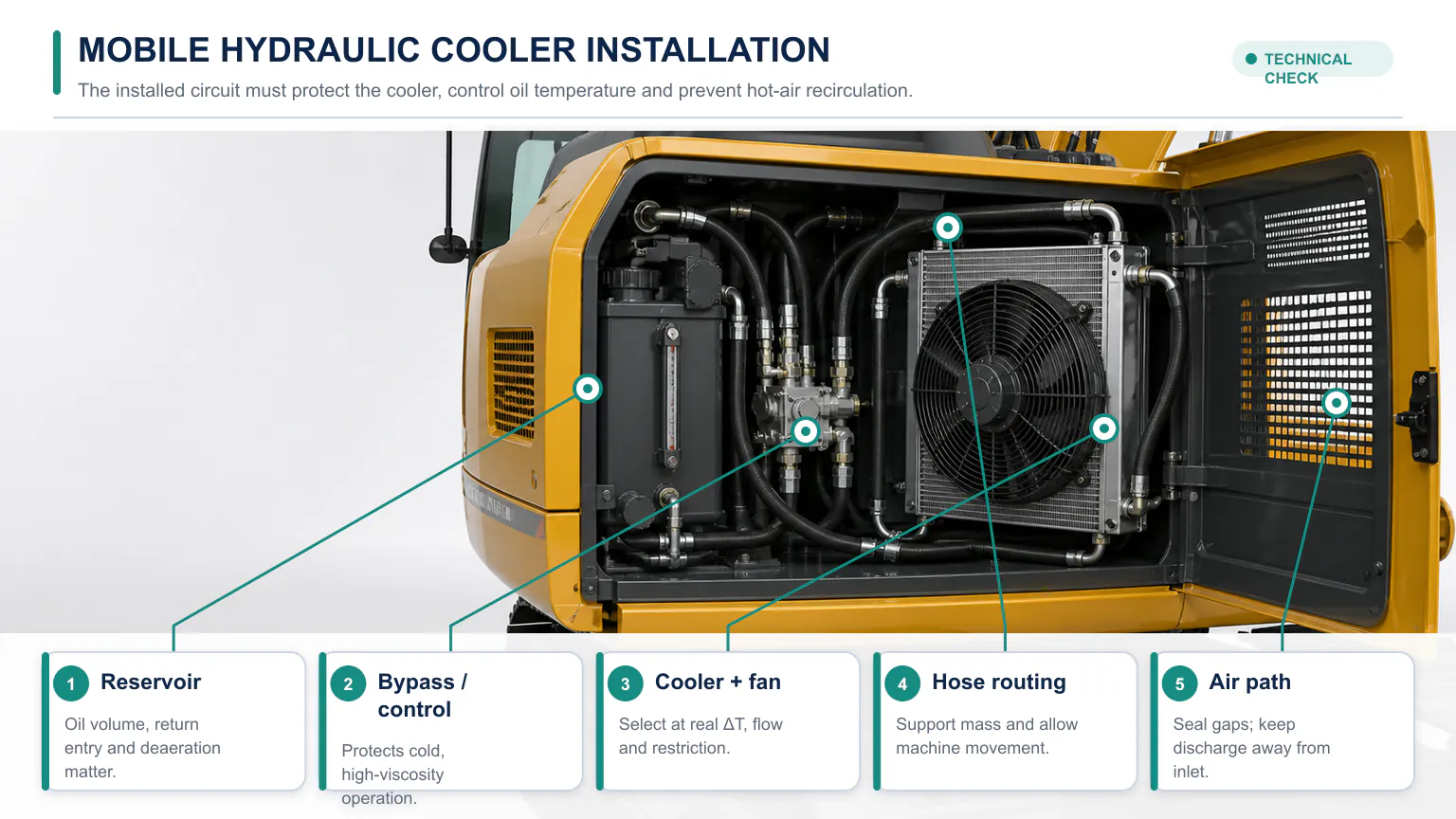
Check both hot operating viscosity and cold-start viscosity. A cooler that drops only 0.5 bar at hot oil can produce much higher backpressure when cold. The core, filter, seals, return line, and component cases must remain protected. A bypass valve or thermostatic bypass allows cold viscous oil around the core until conditions are suitable, but its cracking pressure, capacity, leakage, and temperature control must be selected.
Give the supplier heat load, oil flow, oil inlet/target temperature, air inlet temperature, oil viscosity, fan condition, and environment. Select a cooler whose corrected heat rejection is at least the required load with an engineering margin appropriate to data uncertainty, fouling, production tolerance, and aging. Do not add a blanket percentage without explaining it.
At the same operating point, read or calculate oil-side pressure drop and confirm it is below the allowable limit. A cooler can meet heat rejection and still be unacceptable because of backpressure. Moving to a larger core can reduce pressure drop, but fan and packaging behavior must be rechecked.
If the curve is expressed as kW/°C, multiply by the relevant oil-to-air temperature difference under the manufacturer's definition. Confirm whether the rating is based on oil inlet minus air inlet, mean oil temperature, or another convention. If a selection tool outputs a model without calculation evidence, request the input and result record.
The core creates airflow resistance. Choose the fan at the required airflow and static pressure through the installed coil, guard, grille, ducting, and adjacent heat exchangers—not at free air. Verify rotation and whether the fan pulls or pushes through the intended path. Seal gaps that allow air to bypass the core, and prevent hot discharge from returning to the inlet.
For DC fans, check 12/24 V, current at rated voltage and hot condition, startup/inrush, alternator/battery capacity, fuse, wire size, relay/controller, connector, speed control, and environmental rating. For hydraulic fans, define supply pressure/flow, motor efficiency, control valve, reverse function, priority under machine load, and the heat that the fan drive itself adds to the hydraulic system. For engine-driven fans, validate speed ratio, clutch/control, and available power.
Variable-speed control saves power and noise. Place sensors and setpoints so oil remains in the target band without hunting. Define fail-safe action for an open sensor, lost communication, or fan fault. A reversible fan can shed debris but should reverse only under a controlled sequence that avoids overheating and unsafe debris discharge.
Construction machines work in dust, chaff, fibers, mud, vibration, and high ambient. Dense louvered fins may transfer heat well when clean but clog quickly. A more open or non-louvered fin can maintain better field performance. Ask for clean and fouled-service reasoning, not simply maximum laboratory kW.
Mount the cooler with appropriate isolation and support hoses close to ports so pipe mass does not fatigue the header. Allow frame and engine movement. Protect against stones and accidental contact without choking airflow. Provide access to clean both faces and the gaps between stacked coolers. Confirm cleaning pressure and direction so fins are not folded.
On loaders, repeated low-speed high-load cycles can produce heat while ram air is minimal. On excavators, swing, travel, attachment, and standby modes create different losses and fan availability. Validate the worst real work cycle rather than a high-idle no-load test.
The installed circuit must protect against cold-oil pressure, support hoses and prevent hot-air recirculation.
This common arrangement uses oil returning to tank. Check peak return flow, pressure spikes, backpressure limits, filter/bypass interaction, and whether cylinder regeneration creates unexpected flow. The cooler should not impose damaging case or return pressure.
A dedicated pump draws from the reservoir through a cooler and often a filter. Flow is stable and cooling can be controlled independently of machine functions. Select pump suction, filtration, aeration control, return location, motor power, and shutdown alarms. The offline pump adds its own heat and maintenance.
Some transmissions or closed-loop systems use charge oil for cooling. This requires system-specific engineering to preserve charge pressure and lubrication. Never reroute a cooler based only on hose size.
Engine radiator, charge-air cooler, A/C condenser, fuel cooler, and hydraulic oil cooler may share fans and airflow. Changing one core alters restriction and entering-air temperature for others. Evaluate the complete pack and fan curve.
Assume testing and loss analysis support a design heat load of 18 kW for a loader, including a documented margin. Maximum measured air entering the cooler is 47°C. Maximum desired hot oil entering the cooler is 77°C, so the oil-to-air difference is 30 K. Cooler-circuit flow is 110 L/min of ISO VG 46 oil at operating temperature. Maximum acceptable cooler pressure drop is 1.0 bar hot, and a cold-start bypass is required.
The required normalized performance, if the manufacturer's curve uses kW per degree of oil-inlet-to-air-inlet difference, is 18 / 30 = 0.60 kW/K. That number is only a screening target. The manufacturer must correct for 110 L/min, ISO VG 46 viscosity, selected fan, altitude, guard/duct restriction, and the exact curve definition. The candidate must also remain below 1.0 bar hot pressure drop.
If Candidate A delivers corrected 20 kW but has 1.3 bar pressure drop, it fails the hydraulic requirement. Candidate B delivers 19 kW at 0.8 bar and fits the fan/space, so it may pass with the defined margin. Candidate C delivers 25 kW but needs electrical current the machine cannot supply. Thermal capacity alone does not select the winner.
Record baseline oil temperature, ambient, cycle, pressures, flow where available, fan speed/current, and faults.
Verify installation, mounts, hose routing, port support, bypass direction/settings, sensor location, fan rotation, guards, and airflow seals.
Start cold and monitor cooler differential pressure or relevant circuit pressure to confirm bypass protection.
Run the defined worst-case work cycle to thermal equilibrium.
Record cooler oil inlet/outlet, entering/leaving air, ambient, flow, pressure drop, fan command/speed/power, engine load, and machine performance.
Confirm stable target temperature without excessive cycling, backpressure, cavitation, leakage, noise, or electrical/hydraulic overload.
Repeat after realistic fouling exposure and scheduled cleaning interval.
Inspect mounts, headers, ports, hoses, wiring, and connectors after thermal cycles and vibration.
Machine make/model/serial, engine, hydraulic schematic, current cooler OE number, and photos/drawings.
Measured/estimated heat load with method and uncertainty.
Oil grade, density/specific heat if used, operating/cold viscosity, total volume, and cleanliness target.
Cooler-circuit normal/peak flow, working/transient pressure, and allowable hot/cold pressure drop.
Oil inlet/target outlet or maximum temperature, worst cooler-inlet ambient, altitude, and duty.
Fan voltage/current or hydraulic supply, control, reversible requirement, noise, and electrical protection.
Core/assembly dimensions, ports, mounts, airflow direction, guards, adjacent coolers, and service space.
Dust/debris, corrosion, washdown, vibration, coating, fin type, and cleanability.
Bypass/thermostat, sensors, filter/offline pump, documentation, test, traceability, quantity, and warranty.
For replacement sourcing, Elecdura's broader wholesale oil cooler category can support OE-number and dimensional screening. Final approval should still verify performance or a controlled exact cross-reference.
Published preliminary rules vary, such as 20–30% of installed horsepower or one-third for certain construction/agricultural assumptions. They are rough estimates. Measure heat load or calculate actual losses for final selection.
Not unless the schematic proves that the same flow passes through the cooler. Return, charge, offline, and case-drain circuits differ, and transient return can exceed pump delivery through regeneration.
Pressure drop must stay within system limits, including cold start, but zero is not the only goal. Balance thermal performance, size, cost, flow distribution, and control. Use manufacturer curves at actual viscosity and flow.
Possible causes include high system losses, bypass stuck open, low cooler flow, wrong fan rotation, low fan speed, air recirculation, clogged stacked cores, incorrect temperature data, high ambient, or a rating used at the wrong conditions.
Many mobile systems need cold-start or transient protection, but the requirement and cracking pressure depend on oil viscosity, flow, cooler/core rating, circuit backpressure limit, and machine design. Follow system and cooler engineering.
A defensible selection connects measured heat load to a corrected manufacturer curve and then proves pressure drop, fan power, controls, environment, mounting, and serviceability. It also fixes hydraulic inefficiency before adding cooling. Keep assumptions and units visible so another engineer can reproduce the decision.
For an excavator, loader, or volume replacement quotation, send the machine/OE list, heat-load method, temperatures, flow, oil/viscosity, pressure limits, fan supply, drawings, environment, and annual quantity through the Elecdura contact page. That data allows a cooler to be selected for the operating point rather than by appearance.