English
Views: 0 Author: Elecdura Publish Time: 2026-08-07 Origin: Elecdura
Finding oil in an intercooler does not prove that the turbocharger has failed. A light film can be carried into the charge-air system by normal crankcase ventilation, especially after long service intervals. A measurable pool that returns quickly, blue exhaust smoke, rising oil consumption, damaged compressor blades, or oil concentrated immediately after the turbo demands a different response. The useful question is not simply whether oil is present. It is where the oil entered, how quickly it accumulated, and whether the charge-air cooler can be cleaned safely after the source is corrected.
This diagnosis matters because the on-highway cooling system and an off-highway machine may use different hose lengths, crankcase ventilation layouts, turbo orientations, and charge-air cooler drain points. The same visible residue can therefore represent normal mist carryover on one engine and active oil delivery on another. Before ordering an aftermarket cooling component, record the evidence under repeatable operating conditions.
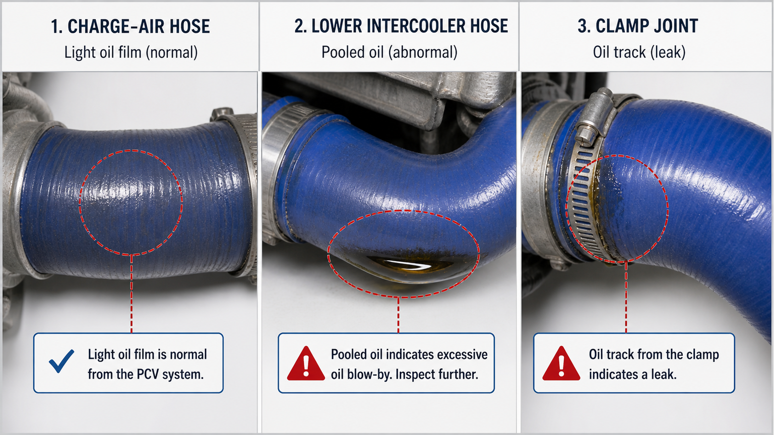
A thin, evenly distributed coating inside the compressor outlet hose can be normal. It becomes suspicious when oil drips from a disconnected lower hose, collects again soon after cleaning, appears with blue smoke or runaway risk, or is accompanied by abnormal turbo shaft movement and compressor-wheel contact. Oil found only at a loose hose joint may also be exposing a boost leak: the joint leaks air, and the normal oil mist marks the escape path.
Evidence | More consistent with normal carryover | More consistent with an active fault |
|---|---|---|
Quantity and distribution | Light film across several pipes | Pooling at the lowest point or fresh wet oil near one source |
Rate of return | Slow accumulation over a long interval | Oil returns after a short controlled run |
Engine behavior | No smoke, stable oil level, normal boost | Blue smoke, oil loss, overspeed concern, or reduced boost |
Turbo evidence | No wheel contact and no abnormal noise | Damaged wheel, housing contact, heavy outlet-side oil, or noisy bearing system |
Hose condition | Dry exterior and secure joints | Swollen hose, soft liner, split, loose clamp, or oil tracking from a joint |
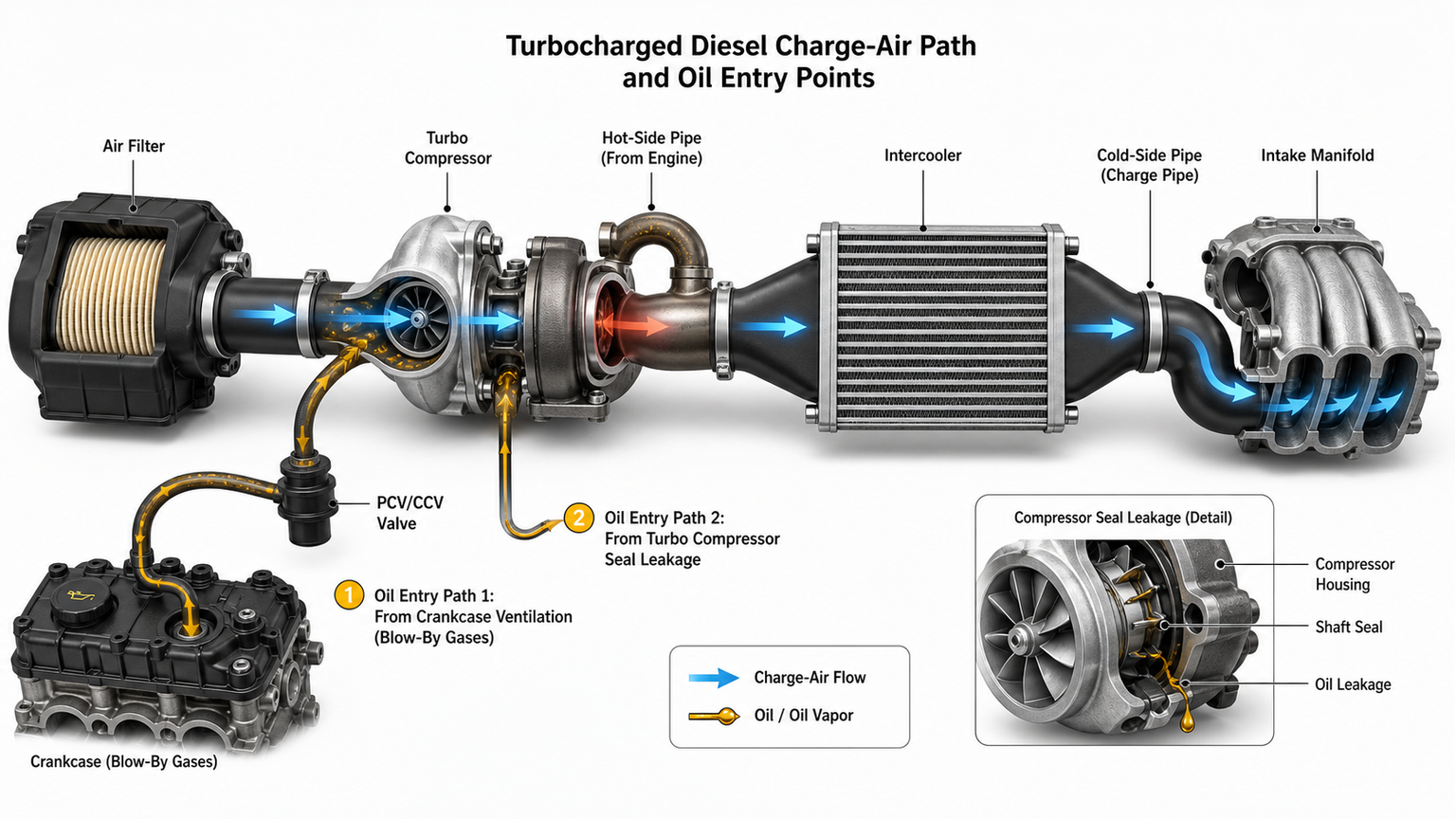
The charge-air path begins at the air filter, passes through the turbocharger compressor, continues through the hot-side pipe and intercooler or charge-air cooler, and returns through the cold-side pipe to the intake. Oil cannot be interpreted without following this direction of flow. Photograph each connection before removal and mark the hot and cold sides so that the location of the heaviest deposit is not lost during cleaning.
Combustion gas that passes the piston rings carries oil aerosol through the crankcase ventilation system. Many engines route this vapor upstream of the turbo compressor. The compressor then disperses the mist through the pipes and cooler. A separator reduces the oil load but does not always remove every droplet. High engine load, excessive crankcase pressure, a restricted separator, incorrect oil level, worn cylinders, or a damaged PCV diaphragm can increase carryover.
Inspect the duct where the breather joins the intake. If fresh oil begins at this junction and continues downstream, examine the separator, drain path, PCV control, crankcase pressure, and engine condition before blaming the turbo. A valve-cover assembly may integrate the separator or diaphragm, so a ventilation fault is not always repaired by replacing a small external valve. Do not infer the permitted crankcase pressure from another engine family; use the engine maker's procedure.
A turbocharger does not rely on a simple stationary lip seal. Its oil control depends on bearing clearances, pressure balance, drain flow, shaft speed, and housing condition. A restricted oil drain, excessive crankcase pressure, coked return passage, damaged bearing system, or compressor-side pressure imbalance can push oil into the intake even when the visible wheel still turns.
Some radial movement can be present when a journal-bearing turbo is dry and stationary, while axial movement and wheel contact carry different significance. Compare the measured condition with the correct service specification. Look for blade damage, witness marks, rotation resistance, oil distribution on both compressor and turbine sides, and the condition of the feed and drain lines. A turbo replaced without correcting a restricted drain or crankcase-pressure fault may contaminate the replacement charge-air cooler again.
Oil can remain in a cooler after a previous turbo failure, an overfilled breather system, or incomplete cleaning. If the source was repaired but the lower tank and hoses were not drained, the next technician may assume the new turbo is leaking. Establish whether the charge-air system was opened or cleaned during the earlier repair. Date the service, document the oil level, and recheck after a controlled interval rather than judging a single snapshot.
Oil on the outside of a cooler can originate from a valve cover, turbo feed line, hydraulic circuit, power-steering hose, or engine-bay spill. Clean the area and use a tracer approved for the correct fluid if necessary. Internal charge-air oil usually escapes at a pressurized joint and follows the pipe or tank seam. External engine oil often runs downward regardless of boost direction. An oil-stained joint also deserves a proper boost-leak test; a loose clamp can cause both performance loss and a misleading oily patch.
Drain the lowest accessible connection into a clean graduated container only when the manufacturer permits it and the system is cool. Recording the recovered amount is more useful than wiping the pipe and describing it as "a lot." There is no universal safe quantity, because cooler volume, pipe routing, service interval, engine displacement, and duty cycle differ. The diagnostic value comes from comparison: hot side versus cold side, before versus after repair, and one controlled interval versus the next.
Inspect the breather inlet, compressor inlet, compressor outlet, hot-side pipe, cooler inlet tank, lower tank, outlet tank, cold-side pipe, and intake connection in sequence. Use separate clean swabs or photographs so that oil is not transferred between locations. The first location with a sharp increase in wetness is often more informative than the dirtiest low point, where gravity naturally concentrates fluid.
Confirm the oil grade, fill level, and distance or hours since the last service. Compare the dipstick on level ground using the specified procedure. Blue smoke under boost, smoke after extended idle, or smoke after deceleration may point to different paths and should not be treated as interchangeable. Also check for diesel fuel dilution or coolant contamination, because an apparent oil-level trend can be distorted by another fluid entering the sump.
Pressure-test the system at the specified low test pressure with suitable plugs, a regulated air source, and a calibrated gauge. Never use uncontrolled shop pressure. Listen and apply approved leak-detection solution to tanks, cores, hose joints, sensor bosses, and clamps. A leaking CAC reduces boost and can draw attention to the oil stain, but the leak does not by itself identify the oil source. For broader heat-exchanger selection, Elecdura's engine cooling parts range shows why the medium and circuit must be identified before replacement.
Oil exposure can soften some elastomers, separate an inner liner, and reduce clamp retention. Flex the hose only as allowed, inspect the inside for blistering or loose layers, and check the bead area for cuts. A hose that looks acceptable outside may collapse or shed material inside. Verify diameter, length, bend geometry, reinforcement, temperature capability, pressure class, and clamp type; appearance alone is not an adequate match.
Clean or replace the affected components, reset the oil level, and define a repeatable duty cycle. Reinspect the same locations after the same distance or operating hours. Recurrence at the compressor outlet supports an upstream source; residue that steadily decreases may have been left from the prior failure. This follow-up is essential before a wholesale buyer rejects a batch of coolers for contamination that entered from the engine.
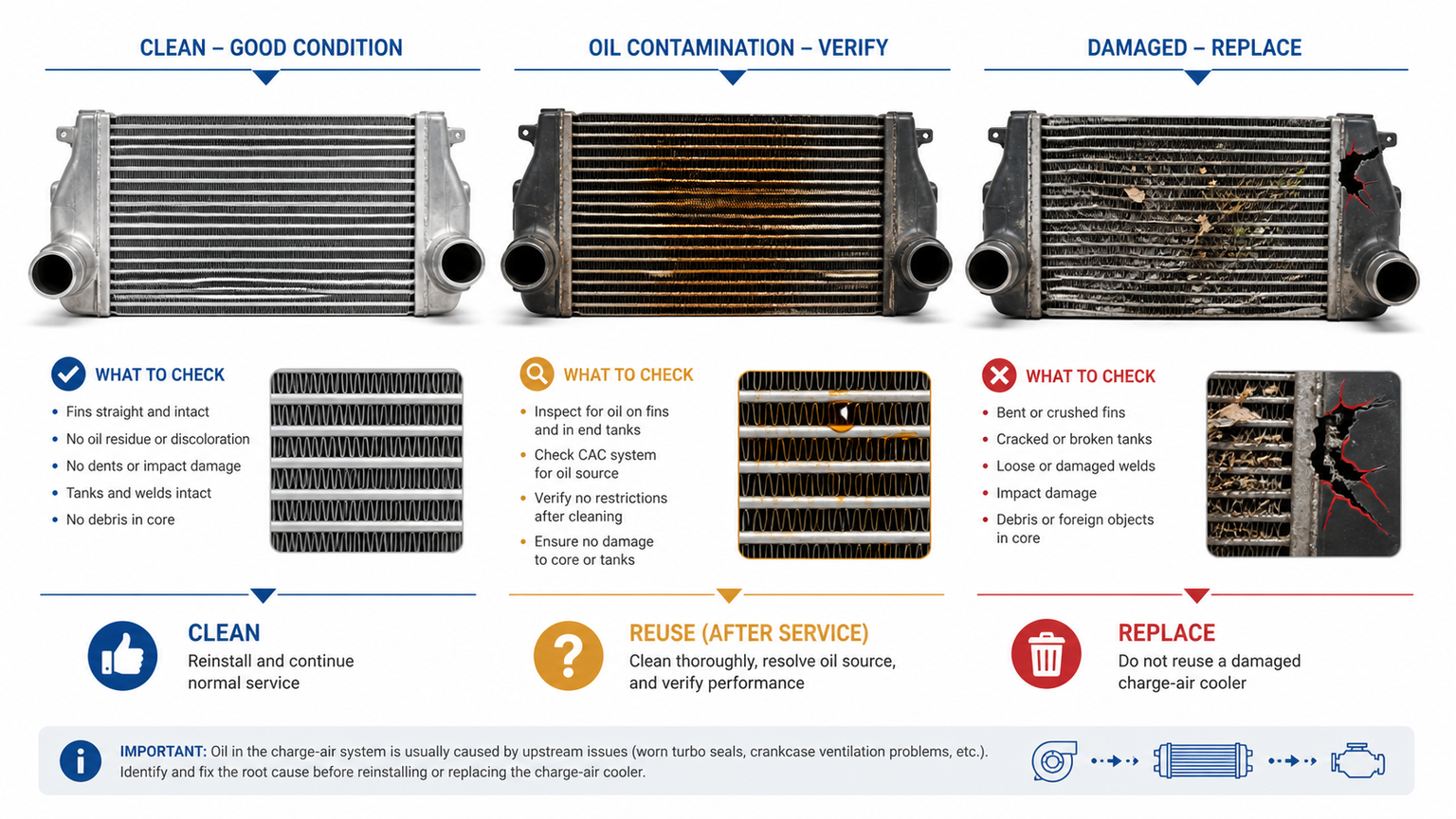
Cleaning is reasonable only when the core is structurally sound, the approved cleaning method can remove the contaminant, and the unit can be dried and pressure-tested completely. The process must not leave flammable solvent, water, lint, or loosened debris in the charge-air path. Follow the vehicle or equipment maker's instructions; some designs or contamination events require replacement rather than field cleaning.
Condition | Preferred action | Reason |
|---|---|---|
Light film, no active source, core passes test | Document and monitor; clean only if required | Unnecessary solvent use can create a new risk |
Recoverable oil, sound metal core, approved process available | Clean, dry, inspect, and pressure-test | Reuse depends on verified cleanliness and integrity |
Metal fragments after turbo failure | Replace unless an approved process proves complete removal | Hidden debris can enter the replacement engine or turbo |
Swollen plastic tank, cracked seam, damaged tube, or failed test | Replace the complete CAC | Cleaning cannot restore structural or sealing integrity |
Unknown solvent compatibility or inaccessible internal passages | Escalate to the maker's procedure or replace | Residual chemical and trapped contamination are unacceptable |
A cooler is not ready because the rinse fluid looks clear. Internal fins, turbulators, and low points can retain liquid. Use the specified drying method and confirm that no liquid remains before installation. Do not heat a plastic-tank unit beyond its material limit. Do not use open flame or a solvent that attacks seals, brazed joints, coatings, or hose material.
When a compressor wheel contacts its housing, fragments can travel into the hot-side pipe and cooler. A visible inlet inspection cannot prove that every internal passage is clean. Debris released later can damage the new turbo, enter the cylinders, or obstruct airflow. The replacement decision should therefore consider the failure mode, not just whether the cooler holds pressure.
Do not order a CAC from width and height alone. Similar cores may use different tank depth, inlet diameter, outlet diameter, port direction, mounting brackets, sensor bosses, drain provisions, core thickness, and pressure capability. The aftermarket product program covers varied applications, but each quotation still requires application-specific evidence.
OE reference from the cooler and the vehicle or equipment parts catalog;
make, model, year, engine code or equipment model, and market version;
overall dimensions and core dimensions measured consistently;
inlet and outlet outside diameters, orientation, and bead design;
mounting-bracket positions and photographs from front, back, top, and both ends;
sensor, drain, or auxiliary port details;
required quantity, destination, packaging expectation, and any sample requirement.
Pressure and temperature capability depend on core construction, alloy, tube geometry, brazing process, tank design, and validation method. A catalog image cannot establish those ratings. Ask for the drawing and test basis associated with the exact part number. If the application is uncertain, use the catalog resources as a starting point and confirm the physical unit before bulk approval.
For a wholesale heat-exchanger program, define inspection criteria that match CAC risk: protected ports, clean internal passages, straight mounting points, undamaged fins, controlled weld or crimp appearance, correct accessories, traceable labels, and packaging that prevents the ports from striking the carton. Sampling should include dimensional comparison and a pressure/leak test based on the agreed drawing and specification.
Separate the charge-air cooler inspection from the liquid-cooler inspection plan. A radiator is checked for coolant-side connections, cap or expansion routing, and fan-side clearance, while a CAC is checked for boost-air cleanliness, hose retention, and pressure loss. Likewise, the residue and line risks described in Elecdura's transmission oil cooler leak guide belong to a lubricating-fluid circuit, not the intake stream. Keeping these inspection plans separate prevents a supplier or warehouse from applying the wrong plugs, cleaning fluid, leakage criterion, or labeling to a visually similar heat exchanger.
Do not treat an oil cooler, engine oil cooler, or hydraulic oil cooler as interchangeable with a CAC. They carry different media and may use different cleanliness, pressure, and connection requirements. The oily appearance inside a charge-air cooler does not change the identity of the circuit.
This ignores crankcase ventilation and service history. Establish the entry point, recurrence rate, and supporting turbo evidence first.
A new cooler will collect oil again if the breather, turbo drain, crankcase pressure, or turbo bearing system remains faulty. The source repair and the contamination decision are separate work orders.
Handling, corrosion, chemical exposure, and the original failure may reveal or create a leak. A dry, clean appearance does not prove the core is sealed.
Gravity sends liquid to the lowest section, where a softened liner or loose clamp may retain a dangerous amount. Inspect and replace compromised hoses before the engine is returned to load.
Yes. A light film from crankcase aerosol can be normal. Pooling, rapid recurrence, blue smoke, oil consumption, turbo damage, or hose deterioration requires diagnosis. No single volume applies to every system.
Oil itself can foul surfaces and damage hoses, but low boost more often comes from a leaking joint, split hose, cracked cooler, control fault, exhaust restriction, or turbo problem. Pressure-test the complete charge-air path.
Use only the vehicle, equipment, or cooler maker's approved method. The unit must be completely dry, free of debris, and pressure-tested before installation. Replacement is safer when debris removal cannot be proven.
Replacement is strongly justified when metal fragments entered the CAC, internal passages cannot be verified clean, tanks or tubes are damaged, or the unit fails its leak test. A cleanable oil-only event may permit reuse under an approved procedure.
Send the OE number, application and engine details, dimensional drawing or measurements, inlet and outlet photos, mounting points, sensor or drain ports, required quantity, destination, and packaging requirements. Elecdura can then review the request through its contact team without guessing from a generic product image.
Treat oil in the intercooler as evidence to be mapped, not a verdict. Identify the first wet location, quantify recurrence, test the breather and turbo conditions, pressure-test the charge-air path, and inspect every oil-exposed hose. Only then decide whether the CAC should be monitored, cleaned and verified, or replaced. For replacement matching, submit the OE reference, application, port and bracket details, contamination history, and required quantity so the proposed cooler addresses both fitment and failure risk.