English
Views: 0 Author: Elecdura Publish Time: 2026-08-13 Origin: Elecdura
An automotive AC condenser fan not working can be a failed motor, but it can also be a system that never requested fan operation. Low refrigerant pressure, an implausible pressure-sensor signal, ambient-temperature logic, engine protection, a relay or PWM module fault, voltage loss, connector heat, a seized blade, or incorrect fan architecture can all produce a stationary fan. The diagnosis should move in the same direction as the electrical system: request, permission, command, power delivery, motor current, blade movement, and actual airflow.
This architecture-first approach matters because some vehicles use a dedicated condenser fan, some use one shared engine-cooling fan, and others use a dual-fan assembly with staged or variable-speed control. Elecdura's automotive condenser fan range includes different motor, blade, shroud, connector, voltage, and mounting configurations. A fan that fits the opening is not necessarily controlled or loaded correctly.
First confirm that the vehicle is supposed to run the fan under the exact test conditions. Read the A/C request, compressor permission, refrigerant-pressure value, coolant temperature, ambient temperature, and fan command. If a command exists, test voltage and ground at the fan under load, then measure current and airflow. If no command exists, diagnose the input or control logic before replacing the motor.
Command state | Power/current state | Most useful branch |
|---|---|---|
No fan command | Not applicable | A/C request, pressure data, temperature inputs, controller permission |
Command present | No voltage at motor | Fuse, relay, module, harness, connector, control output |
Command present | Voltage present, near-zero current | Open motor winding, connector contact, internal electronics |
Command present | High current, no rotation | Seized motor, blade obstruction, bearing or shroud contact |
Command present | Fan rotates but airflow is weak | Low speed, wrong rotation, blade/shroud mismatch, recirculation |
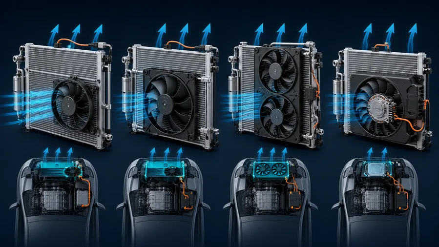
Image 1: Identify the vehicle's fan architecture before electrical testing.
A dedicated electric fan is mounted to move air through the condenser and may operate independently from the engine-cooling fan. Its command can come from a pressure switch, relay logic, body controller, engine controller, or dedicated module. The absence of this fan can cause good cooling at road speed and poor cooling at idle because vehicle motion temporarily replaces the missing forced airflow.
Many transverse-engine vehicles place the condenser ahead of the radiator and use one shared fan or shroud assembly. The controller selects speed based on A/C pressure, coolant temperature, vehicle speed, and other requests. A low-speed circuit can fail while high speed still works, or a PWM module can limit output. Review Elecdura's radiator cooling fan assemblies to see why a motor, resistor, module, shroud, and blade may form one application-specific unit.
Two fans may operate in series for low speed and parallel for high speed, or each fan may have an independent relay or module. One failed motor can change both speeds on a series circuit. A technician who powers only one motor directly may miss a relay-network or companion-motor fault. Use the wiring diagram for the exact vehicle.
A modern fan may receive battery power, ground, and a PWM or LIN command. It can contain internal diagnostics and protection. Applying power to the wrong pin or bypassing the control input can damage the assembly. Verify the protocol and use scan-tool commands where supported.
A control-panel request can be blocked by a climate-control fault, low voltage, engine protection, ambient-temperature limit, or network communication issue. Confirm the request in scan data at each relevant module rather than assuming that an illuminated A/C button equals compressor and fan permission.
If the system has lost most of its charge, the controller may inhibit the compressor and may not request condenser airflow. The stationary fan is then a consequence, not the cause. Inspect for leakage and compare the pressure-sensor value with calibrated gauges. The automotive AC pressure switch and sensor range includes binary, trinary, and analog devices that cannot be tested by one universal bypass method.
A failed reference circuit, poor ground, corroded connector, signal short, or biased sensor can make the controller believe pressure is unsafe or unnecessary. Compare key-on engine-off sensor data with actual static pressure and refrigerant temperature. Do not replace the fan because the controller is responding to false input.
Some strategies reduce fan demand at road speed. A fan that does not run during a highway check may be normal. Reproduce the complaint at idle or use an approved bidirectional command. Conversely, cooling that works only while driving strongly supports an airflow investigation but does not isolate the motor.
A fuse opens because current exceeded its rating or because a fault heated the link; replacing it is not the diagnosis. Inspect for a seized motor, harness short, water intrusion, chafing, incorrect fuse value, or internal module fault. If the fuse is intact, test power on both sides under the commanded condition.
Confirm coil command, coil ground, contact supply, and contact output. A relay can click while its contacts create excessive resistance. Measure voltage drop across the closed contacts with the fan drawing current. Series/parallel systems may use several relays; label each state before moving parts.
Measure from battery positive to the motor positive terminal and from the motor ground terminal to battery negative while the fan is commanded. This separates supply and ground loss. An unloaded connector can show nominal voltage through corrosion or a partially broken conductor, then collapse when the motor draws current.
Discoloration, melted plastic, relaxed terminals, and oxidized strands show resistance and heat. Determine whether terminal tension, water ingress, poor crimping, motor overcurrent, or repeated high-temperature operation caused the damage. Replacing only the connector while retaining an overcurrent motor can create another failure.
Use an appropriate current clamp and service information. A stationary motor with high current suggests mechanical lock or a shorted winding. Near-zero current with correct loaded voltage suggests an open circuit or internal electronics fault. Excessive steady current with slow rotation suggests bearing drag, blade contact, or winding damage. Compare cold inrush and warm running behavior.
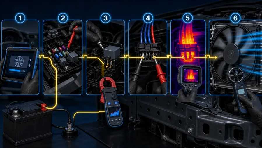
Image 2: Test the energized circuit, not only disconnected components.
A spinning fan can still fail the system. Check rotation direction, blade pitch, motor speed, shroud sealing, core coverage, air recirculation, and obstruction. A replacement blade installed backward can move air in the wrong direction. A shallow or incorrectly positioned blade can recirculate air around the shroud instead of pulling it through the condenser.
With the system safely operating, compare high-side pressure before and after a verified fan command or controlled airflow increase. A pressure response supports an airflow relationship. If pressure remains abnormally high despite strong airflow, investigate charge quantity, non-condensables, condenser restriction, line restriction, and ambient heat load. The AC condenser core must be clean externally and capable of internal heat transfer.
Debris can hide between the condenser and radiator. Bent fins, foam seals, damaged air guides, or an incorrectly fitted shroud can divert air. The radiator, condenser, and intercooler comparison helps identify each core before cleaning or replacement.
Note whether cooling fails at idle, in traffic, at road speed, during high ambient temperature, or after a warm restart. Record vent temperature, refrigerant pressures, engine coolant temperature, ambient temperature, fan command, compressor command, and battery voltage.
Use the VIN, wiring diagram, OE reference, and physical inspection. Determine whether the fan is dedicated, shared, dual, resistor-controlled, relay-staged, PWM, LIN, or module-integrated. Do not assume that the larger fan belongs only to the radiator.
Check A/C request, pressure, coolant temperature, ambient input, fan target, and diagnostic codes. If the command is absent, diagnose the reason. If command is present, continue downstream.
Measure loaded voltage, voltage drop, relay output, fuse integrity, and terminal condition. Wiggle-test only when safe and watch the current or voltage trace for interruption.
Compare inrush, stabilized current, and speed with service data or a known-good identical application. Listen for bearing noise and inspect blade clearance. A radiator or condenser fan motor must be matched by electrical and mechanical load, not diameter alone.
After correcting the fault, operate the system at the complaint condition. Confirm pressure control, vent temperature, coolant temperature, fan staging, connector temperature, and stored-code status. The repair is not proven by fan rotation alone.
What is seen | Common wrong conclusion | Better discriminator |
|---|---|---|
Fan is off with A/C button on | Fan motor is failed | Scan fan command and pressure permission |
Fan runs with direct battery power | Motor is fully healthy | Loaded current, warm behavior, speed and airflow |
Relay clicks | Relay contacts are good | Voltage drop across energized contacts |
Fan spins slowly | Low command is normal | Target speed, current, pressure response |
High pressure at idle | Fan is the only cause | Airflow verification plus charge and condenser tests |
Replace an individual motor when it is separately serviceable, the blade and shroud are undamaged, the mounting and balance can be restored, and the connector and control hardware are compatible. Replace a module when command, power, ground, and motor tests isolate the module and the module is offered separately for the application. Replace the complete assembly when electronics are integrated, the shroud is distorted, blade balance is uncertain, mounts are damaged, connectors have system-level heat damage, or labor and warranty risk make component mixing unsuitable.
The fan assembly versus motor versus module guide provides a broader service-boundary comparison. This page's decision should remain anchored to the A/C condenser airflow command and measured electrical state.
Before discarding the old motor, record cold inrush, running current, resistance to ground where applicable, blade drag, connector temperature, and the condition of the harness. A failed module may be secondary to motor overcurrent. A new module connected to the same dragging motor can fail again, while a new motor installed on a heat-damaged high-resistance connector can run slowly and overheat.
If the fan failed during a high-pressure event, inspect the condenser for external blockage, damaged fins, internal restriction, and integrated receiver-drier requirements. Use the AC condenser leak-test methods when leakage is suspected. Fan repair and condenser repair answer different questions, even when both influence discharge pressure.
A pressure-related shutdown can also make the compressor appear intermittent. The AC compressor short-cycling guide shows how command and pressure traces distinguish protective cycling from clutch or compressor failure.
A motor, relay, module, or connector can pass while cold and fail after under-hood temperature rises. Operate the repaired system long enough to reproduce the original thermal condition, then repeat fan command, loaded voltage drop, current, speed, high-side pressure, and vent-temperature checks. Inspect the connector with an appropriate temperature method and confirm that harness routing keeps it away from sharp edges and exhaust heat.
For a dual-fan system, command every available stage and verify that one motor does not backfeed or force the other through an unintended path. Confirm that both blades stop without shroud contact and restart consistently after a warm shutdown. These final checks protect a new module from a companion motor that was not included in the first diagnosis.
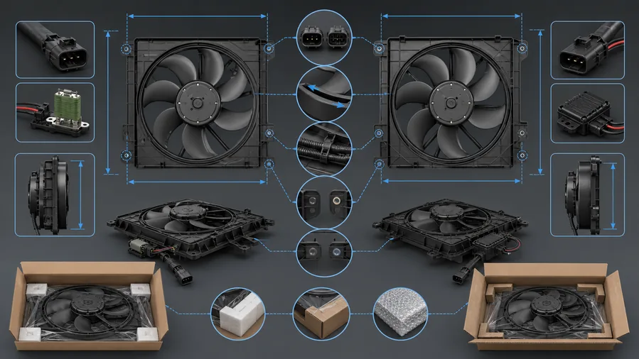
Image 3: Matching points for a motor, module, or complete fan assembly.
Provide the OE number, vehicle, model year, engine, cooling package, market version, and whether the fan is dedicated or shared. Record overall shroud dimensions, blade diameter and rotation, motor voltage, connector shape and pin count, resistor or module part number, mounting points, harness length, condenser/radiator position, and whether the assembly includes relays or air guides.
For a dual assembly, identify left and right positions from the driver's perspective used by the application documentation, not from a loose part on a bench. Confirm whether motors are identical, whether one module controls both, and how low and high speeds are generated. Elecdura's wholesale condenser fan program and wholesale cooling fan range use these details to separate similar-looking assemblies.
Packaging must protect the shroud corners, blade clearance, connector locks, and module heat sink. For volume orders, approve a sample with static fit, connector engagement, current, rotation, vibration, and airflow-related system response before full release. Review Elecdura's aftermarket supply options for distribution and private-label requirements.
Keep the automotive air-conditioning parts overview as the parent context for pressure switches, condensers, compressors, driers, and fans. This avoids turning a fan article into a generic cooling-fan page while still supporting the complete A/C repair decision.
For shared-fan systems, compare the requested unit with the wholesale AC condenser range and radiator layout so bracket, core, shroud, and line clearance are checked together before sample approval.
Send the OE reference, application, fan and connector photographs, shroud measurements, command and loaded-voltage results, current reading, failed component boundary, and quantity through the Elecdura contact page. This evidence prevents a control fault from becoming an unnecessary fan order and prevents a correct diagnosis from being followed by a mismatched assembly.
Not on every vehicle or under every condition. The controller may use pressure, temperature, speed, and protection logic. Verify the command for the exact system.
Yes. If pressure is below the enable threshold, the controller may inhibit both compressor and fan requests. Repair the leak and confirm charge before blaming the motor.
Road speed can provide condenser airflow that a failed or weak fan does not provide at idle. Confirm fan command, airflow, and pressure response because condenser blockage can create a similar pattern.
Yes. It may run too slowly, draw excessive current, fail when hot, vibrate, or produce inadequate airflow. Measure current, speed, and system response.
Insufficient airflow can raise discharge pressure and compressor load. Protection may cycle or disable the compressor, but repeated high-pressure operation can increase heat and stress.
A stationary condenser fan is the middle of a diagnostic chain, not the conclusion. Identify the architecture, verify the A/C and pressure request, trace the energized circuit under load, measure current and airflow, and confirm the refrigerant-pressure response. Only then choose the motor, module, or complete assembly that matches the verified service boundary.